In the years when engines were a lot easier to work with a ballast resistor was used in order to prolong the life of the coil. Locate ballast resistor along firewall.
Car Electrical Diagram Electrical Wiring Diagram Electrical Diagram Electrical Wiring
These coils had very simple wiring.

Ballast resistor 12 volt ignition coil wiring diagram. The purpose of an ignition ballast resistor between the ignition switch 12v and the ignition coil positive terminal is to restrict current flow through the ignition coil. Some customers report that bypassing the ballast resistor by disconnecting the ballast feed wire from the starter solenoid or built into the loom and providing a direct 12 volt feed from the starter solenoid relay or fuse box to the ignition coil has proved to be a success and has given good results. Ignition coil ballast resistor wiring diagram welcome to my internet site this blog post will certainly discuss concerning ignition coil ballast resistor wiring diagram.
The spark plug wire the power wire and the ignition switch wire. Ignition coil ballast resistor wiring diagram with ignition coil ballast resistor wiring diagram image size 609 x 360 px and to view image details please click the image. Wiring diagram for ignition coil.
The typical automotive ignition system prior to 1974 consisted of a coil and ballast resistor with breaker points to interrupt the current flow when a spark was needed. Here are a few of the top drawings we get from various sources we wish these photos will certainly be useful to you and ideally really pertinent to exactly what you want concerning the ignition coil distributor wiring diagram is. Dec 10 2016 automotive wiring diagram resistor to coil connect to distributor wiring diagram for ignition coil.
Since the resistor lowers the overall current 3 volts you want to use a coil that will not be bogged down by the lower current. Older model cars used the 12 volt ignition coils to provide power to the spark plugs. They usually required only three wires.
Failure to use an ignition ballast resistor will eventually destroy the ignition module. This simple system is easy for even the novice mechanic to wire. Coil figure 1 unilite wiring diagram using ballast resistor note.
Ignition coils of this type are usually a little larger than a soda can and are heavy. 800 x 600 px source. Determine whether the coil is a 9 volt or a 12 volt coil.
The best location for the ballast resistor to be connected is close to the coil along the firewall. Here is a picture gallery about ignition coil ballast resistor wiring diagram complete with the description of the image please find the image you need. Ignition coil distributor wiring diagram size.
The job of the ballast resistor was to inhibit current to a level that would not overheat the coil.

Farmall 450 Gas Generator Altern Yesterday S Tractors Alternator Gas Generator Farmall

Battery Ignition System Parts Circuit Diagram Advantages Disadvantages Pdf In 2020 Ignition System Ignite System

Lumenition Optronic Ignition System For Vintage Classic Cars Ignition System System Ignite

Http Www Objext Com Wiring Diagramir Jpg Automotive Electrical Electrical Wiring Diagram Electrical Wiring

Ford Tractor Ignition Wiring Diagram Allis Chalmers Wd 12 Volt Ford Tractors Tractors 8n Ford Tractor

Automotive Wiring Diagram Resistor To Coil Connect To Distributor Wiring Diagram For Ignition Coil Wiring Diagram For Ig Ignition Coil Ignite Ignition System

Ignition Coil Ballast Resistor Wiring Diagram Helloo

Wiring Diagram For Ignition Coil

Ford Tractor Ignition Wiring Diagram Allis Chalmers Wd 12 Volt Ford Tractors Tractors 8n Ford Tractor

Car Starting Procedure Auto Body Work Vw Syncro Auto Body

Ford Duraspark 2 Ignition Automotive Mechanic Car Mechanic Automotive Repair

Ford Tractor 12 Volt Conversion Free Wiring Diagrams 9n 2n Ford Tractors Tractors 8n Ford Tractor

Ammeter Wiring 3 Wire Alternator To Chevy Alternator Automotive Electrical Diagram

Ford Ranger Duraspark Ii Ignition Basics Ford Ranger Wire Diagram

Alternator Coil Alternator Gas Generator Farmall

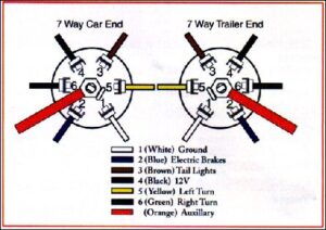
Wiring Diagram Cars Trucks Wiring Diagram Cars Trucks Truck Horn Wiring Wiring Diagrams Trailer Wiring Diagram Trailer Light Wiring Diagram
Vw Distributor Wiring Diagram Wire Resistors Coil

65 Chevy C10 Wiring Diagram 1965 Truck Diagrams Plete 73 Png 2 000 1 525 Pixels Motorcycle Wiring Electrical Diagram Car Alternator

How To Start A Cold Engine On A 1969 Ford F100 Many 1970 And Later Harnesses Already Have A Fused 12 Volt Feed In The Harnesses Tha In 2020 Diagram Ignition Coil Wire