For complete instructions on wiring a basic 4 way switch see our wiring a 4 way switch article. A two wire cable c2 is run from the light to the first switch sw1 and a 3 wire cable runs between all the switches.
Wiring 4 Lights 3 Way Switch Www Light Switch Wiring 3 Way Switch Wiring Three Way Switch
Wiring 3 switches and 2 lights.

4 way switch wiring diagram 2 lights. 4 way switches have four terminals each with two pairs of travelers one set usually black and one set usually brass color. Wiring a 4 way switch is simply adding a switch to an already existing 3 way switch circuit. Power from light fixture to light switch.
How to wire a 4 way switch. For a 4 way light circuit to work you need two 3 way switches and at least one 4 way switch. Do you need a 3 way switch wiring diagram.
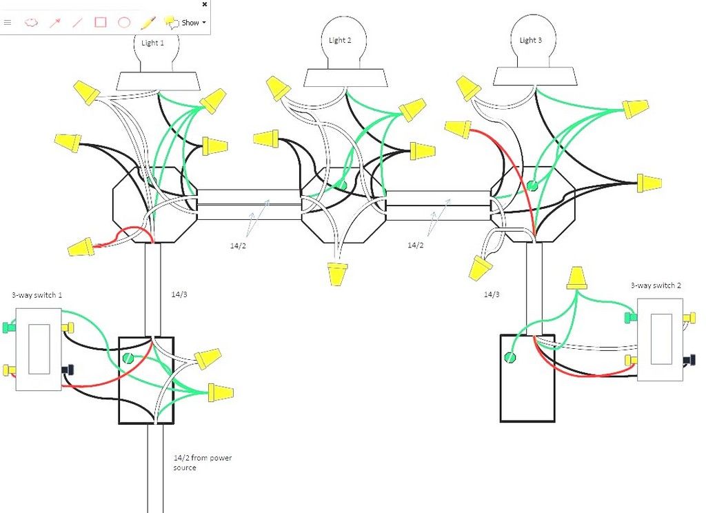
This drawing shows the wiring for multiple lights in a 4 way switch circuit with the source and fixtures coming before the switches. The 4 way is used when you want to control the light or lights from two or more locations. Four way switch wiring diagram with the line and the load in the same switch box.
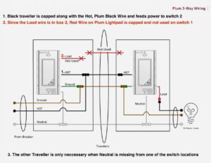
This diagram is a thumbnail. The white wire needs to be re identified as a hot conductor because it is not being used as a neutral in this installation. In the diagrams below the first switch 3 way common terminal connects to.
This circuit diagram shows wiring for a 4 way circuit with the power source at the light fixture and the switches following. First of all we need to go over a little basic terminology on switches. In the diagram above splices are made and a three conductor cable is installed between all the switches.
In this method the power source is at the light fixture and the two 3 way switches follow after the light fixture. Place all the 4 way switches between the two 3 way switches. If you want more than three locations to control the lights you will need a 4 way switch for each of those extra locations.
A 4 way switch wiring diagram is the clearest and easiest way to wire that pesky 4 way switch. Conventional 4 way switch wiring. A four switch configuration will have two 3 way switches one on each end and two 4 way switches in the middle.
4 way switch wiring diagram with the power feed through the light. To view it at full size click on the diagram. This allows you to control a load from other locations in addition to the 2 locations that a 3 way circuit provides.
I have a few of the most common ways in wiring a 4 way switch to help you with your basic home wiring projects. Click here to access note. More lights can be added to this circuit by duplicating the wiring shown here for each additional fixture.
Quick 4 way light wiring. A 2 wire cable is connected from the light fixture to the first 3 way switch.

Fine 3 Way Wiring Multiple Lights Photo Simple Diagram Within Two To One Switch Light Switch Wiring 3 Way Switch Wiring Three Way Switch

Wiring Diagram For 3 Way Switch With Multiple Lights Http Bookingritzcarlton Info Wiring Diagram For Light Switch Wiring Electrical Wiring Diagram Switches

Wiring Diagram For 3 Way Switch With Multiple Lights Home Electrical Wiring Light Switch Wiring 3 Way Switch Wiring

3 Way And 4 Way Switch Wiring For Residential Lighting Tom Remus Electric 3 Way Switch Wiring Light Switch Wiring Electrical Wiring

4 Way Switch Wiring Diagrams Light Switch Wiring Installing A Light Switch 3 Way Switch Wiring

Wiring Diagram For 3 Way Switch With 4 Lights Http Bookingritzcarlton Info Wiring Diagram For 3 W Light Switch Wiring 4 Way Light Switch Electrical Switches

4 Way Light Switch Wiring Diagram Multiple Light With Power Feed Via Light Jpg 725 431 Light Switch Wiring Electrical Wiring Diagram 4 Way Light Switch

4 Way Switch Wiring Diagram Home Electrical Wiring Electrical Wiring Light Switch Wiring

Wiring Diagram For 3 Way Switch With Multiple Lights Http Bookingritzcarlton Info Wiring Diagram F Home Electrical Wiring Diy Electrical 3 Way Switch Wiring

Electrical Engineering Books 4 Way Switch Wiring Diagram Light Switch Wiring Electrical Wiring 3 Way Switch Wiring

4 Way Switch Wiring Diagram Multiple Lights Aol Image Search Results Light Switch Wiring Electrical Wiring 3 Way Switch Wiring

Wiring Diagram For 3 Way Switch With 2 Lights Bookingritzcarlton Info Light Switch Wiring 3 Way Switch Wiring Three Way Switch

Image Of Wiring Diagram For House Light A Simple Two Way Switch Used To Operate Two Lights With Th Home Electrical Wiring Electrical Wiring Light Switch Wiring

4 Way Switch Wiring Diagram Home Electrical Wiring Electrical Wiring Light Switch Wiring

2 Way Switch Multiple Light Wiring Diagram 2 Light Light Switch Wiring Electric Lighter Light Switch

Stunning 4 Way Switch Wiring Diagrams Light In The Middle S Light Switch Wiring Electrical Switches 3 Way Switch Wiring

4 Way Switch Wiring Diagram Readingrat Net Inside Four Light Switch Wiring Electrical Wiring 3 Way Switch Wiring
4 Way Switch With Power Feed Via The Light How To Wire A Light Switch Electrical Switch Wiring Light Switch Wiring Three Way Switch

3 Way Switch Wiring Diagram Light Switch Wiring 3 Way Switch Wiring Three Way Switch