Check out this sump pump diagram for more details. Sometimes the float doesn t travel up far enough and therefore doesn t engage the pump.
Wiring Diagram For 220 Volt Submersible Pump Http Bookingritzcarlton Info Wiring Diagram For 220 Volt Submersible P Jet Pump Well Pump Submersible Well Pump
Collection of 3 wire submersible pump wiring diagram.

Sump pump wiring diagram. High end sump pump. Https amzn to 2pkmnsl sewage septic pump. In this article we will discuss the correct way to hard wire a float switch to a submersible pump in order to achieve automatic operation.
Submersible pumps use float switches to perform automatic operation. 3 backlit bilge rocker switch wiring diagram. Of the three bilge pump switches the only one that s not extremely simple is the backlit auto manual bilge pump switch.
Therefore it is suitable for not. This is a simple sump pump control circuit. It reveals the elements of the circuit as simplified shapes and also the power as well as signal links between the tools.
Https amzn to 2pnw21m audible alarm with float. If your pump has a motor surge output of 10 amps use a 15 amp circuit breaker in the breaker panel to allow it enough power to start up but not enough power to burn up if something goes wrong. Learn more about how our awesome backlit switches work here even that one is still pretty straight forward though here are some diagrams that show the single jumper required on the back of the switch.
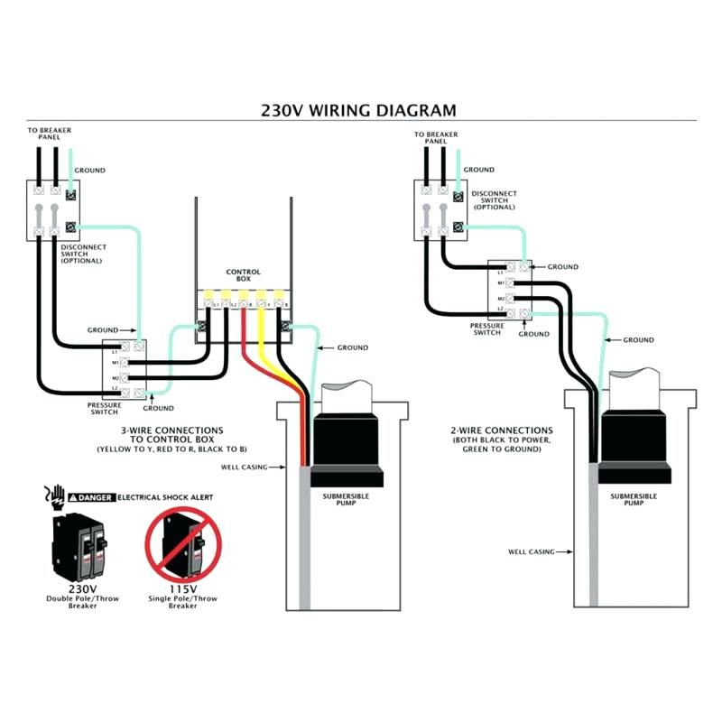
Https amzn to 2wleune alarm with light. Single phase wiring diagrams single phase wiring diagram for 0 5hp pumps with governor switch single phase wiring diagram with governor switch single phase wiring diagram without governor switch three phase wiring diagrams three phase 208v wiring diagram three phase 230v wiring diagram three phase 460v wiring diagram three phase 575v wiring diagram kb pump wiring diagrams kb pump 230v wiring. It shows the elements of the circuit as simplified forms and also the power as well as signal links between the devices.
A wiring diagram is a simplified conventional photographic representation of an electrical circuit. A wiring diagram is a streamlined traditional photographic representation of an electrical circuit. Circuit by thomas kim the advantage of this circuit is no standby current.
Collection of sump pump wiring diagram. The float switch moves with the water level in the tank and this determines when the pump turns on and shuts off. How to create a pump control circuit automatically empty tank float switch installation wiring diagrams apg schematics and of duplex with single sg 4675 on lift station diagram get ac 7071 further sump level madison company sim three phase simplex panel see water inc base website submersible well lovetoknow how to create a pump control circuit automatically empty read more.
The reason i don t like tethered floats especially in colder climates is because colder water stiffens the wire or tether between the pump and float. When you are wiring sump pumps you should always use the manufacturer recommended breaker size for the separate circuit that the pump will operate on. Enclosure box i used.

Davey D40va Automatic Sump Pump 02 Gfci Hot Tub Delivery Home Electrical Wiring

Sump Pump Installation Details Yahoo Image Search Results Sump Pump Installation Sump Pump Sump

Disposal Wiring Diagram Electrical Wiring Wiring A Plug Garbage Disposal

Single Phase Submersible Pump Starter Wiring Diagram On Water Control Panel Inside To Submersible Pump Submersible Sump Pump

Three Phase Submersible Pump Wiring Diagram Submersible Pump Electrical Circuit Diagram Submersible

Square D Well Pump Pressure Switch Wiring Diagram Welcome To Be Able To My Website With This Time Submersible Well Pump Well Pump Pressure Switch Well Pump

Wiring Diagram For 220 Volt Generator Plug Bookingritzcarlton Info In 2020 Outlet Wiring Ac Plug Trailer Wiring Diagram

Franklin Electric Control Box Wiring Diagram In 2020 Well Pump Pressure Switch Submersible Well Pump Well Pump

The Complete Guide Of Single Phase Motor Wiring With Circuit Breaker And Contactor Diagram Electrical Circuit Diagram Electrical Wiring Diagram Circuit Diagram

Water Well Control Box Wiring Diagram Submersible Pump Submersible Sump Pump

Wiring Diagram For 220 Volt Submersible Pump Http Bookingritzcarlton Info Wiring Diagram For 220 Volt Sub Submersible Pump Submersible Submersible Well Pump

Green Road Farm Submersible Well Pump Installation Troubleshooting Submersible Well Pump Well Pump Submersible Pump
Basement Watchdog Combination Primary Pump And Backup Sump Pump Model No Dfk961 Installation Diagram Backup Sump Pump Sump Pump Sump

Septic Tank Float Switch Installation 51 With Level Wiring Diagram 1024×919 On Pump 10 Septic Tank Float Switch

Wiring Diagram For 220 Volt Submersible Pump Http Bookingritzcarlton Info Wiring Diagram For 220 Volt Subme Submersible Well Pump Well Pump Submersible Pump

Single Phase 3 Wire Submersible Pump Control Box Wiring Diagram Submersible Pump Electrical Circuit Diagram Submersible

Pump Float Switch Wiring Diagram With Blueprint Images Diagrams Septic Tank 4 Septic Tank Blueprints Trailer Wiring Diagram

Pump Float Switch Wiring Diagram With Schematic On Level B2networkco For Dual Septic Tank 6 9 Well Pump Pressure Switch Submersible Pump Well Pump

Plc Panel Wiring Diagram Http Bookingritzcarlton Info Plc Panel Wiring Diagram Diagram Sump Pump Sump Pump Alarm