The first and most common is the ladder diagram so called because it looks like the symbols that are used to represent the components in the system have been placed on the rungs of a ladder. The quick basic books tell you everything you need to know to wire and troubleshoot heating and air conditioning equipment and controls and nothing you don t need.
New Wiring Diagram Kompresor Ac Diagram Diagramtemplate Diagramsample Diagram Air Conditioning Unit Electrical Circuit Diagram
There are three basic types of wiring diagrams used in the hvac r industry today which are.

Basic hvac wiring diagram. Furthermore this thermostat wiring diagram is specifically for a system with two transformers your system likely only has one transformer as most typical residential systems only use a single transformer for control. How to read ac schematics and diagrams basics august 22 2018 bryan orr no comments we walk through some of the basics and most common symbols associated with reading an air conditioner wiring schematic or diagram. Always refer to your thermostat or equipment installation guides to verify proper wiring.
3 types of electrical wiring diagrams for air conditioning systems. A wiring diagram is a simplified standard photographic depiction of an electrical circuit. Where the power supply is what path the power takes the load component the switch component and a legend for the symbols used in the diagram.
It is the most common type of wiring diagrams. 3 1 the ladder diagram. Variety of hvac fan relay wiring diagram.
We offer simple explanations of how to. Types of wiring diagrams there are three basic types of wiring diagrams used in the hvac r industrytoday. Introduction for air conditioning systems types introduction for types of motors compressors used in air conditioning systems.
From this point forward ladder dia. Note some ac systems will have a blue wire with a pink stripe in place of the yellow or y wire. Because it explains electrical circuits the diagram looks like a ladder which is where the name comes from.
Air conditioning ac contactor control board 1 this diagram is to be used as reference for the low voltage control wiring of your heating and ac system. It reveals the parts of the circuit as streamlined shapes and the power as well as signal connections between the devices. The metering device component 3 on this air conditioning circuit and cycle diagram is the dividing point between the high pressure and low pressure sides of the system and is designed to maintain a specific rate of flow of refrigerant into the low side of the system.
And in article electrical wiring diagrams for air conditioning systems part one i explained the following points. The ladder diagram the line diagram the installation diagram. Importance of electrical wiring for air conditioning systems.
If you have a two stage heat pump then you will also utilize terminal y2 for the second stage. Most ladder diagrams show the following basic components. That is a basic honeywell thermostat wiring diagram for a single stage heat pump.
Wire circuits how to use a meter and wiring diagrams to troubleshoot how to understand. That means there s no math. It is called ladder because the symbols that are.
Split Air Conditioner Wiring Diagram Refrigeration And Air Conditioning Electrical Circuit Diagram Circuit Diagram

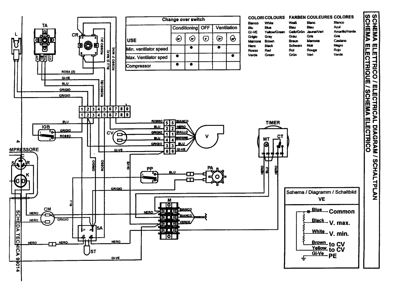
Electrical Wiring Diagrams For Air Conditioning Systems Part Two Electrical Knowhow Electrical Diagram Air Conditioning System Electrical Wiring Diagram

Wire A Thermostat Thermostat Wiring House Wiring Home Electrical Wiring

The 8 Best Ac Wiring Diagram Samples Https Bacamajalah Com The 8 Best Ac Wiring Diagram Samples Ac Electrical Circuit Diagram Ac Wiring Ac Capacitor

New Bryant Gas Furnace Wiring Diagram Diagram Diagramsample Diagramtemplate Wiringdi Electrical Circuit Diagram Thermostat Wiring Electrical Wiring Diagram

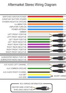
Ac Wiring Diagram Of Window Airconditioner Ac Wiring Thermostat Wiring Wire

Unique Wiring Diagram Air Conditioning Compressor Thermostat Wiring Circuit Diagram Electrical Circuit Diagram

Wiring Diagram Ac Cassette Diagram Diagramtemplate Diagramsample Ac Wiring Electrical Circuit Diagram Electrical Wiring Diagram

Wiring Diagram Intertherm E2eb 012ha Goodman Entrancing Electric Furnace On For Thermostat Wiring Electric Furnace Carrier Furnace

Wiring Diagram Carrier Air Conditioner Wiring Diagram Outside Ac Thermostat Wiring Electric Furnace Ac Wiring

Basic Hvac Wiring Diagrams Schematics At Diagram Pdf Diagram Diagram Design Hvac

Electrical Wiring Diagrams For Air Conditioning Systems Part One Electrical Knowhow Electrical Diagram Air Conditioning System Electrical Wiring Diagram

Control Wiring New Basic Hvac Control Wiring Schema Wiring Diagram Thebrontes Co Unique Co In 2020 Electrical Circuit Diagram Basic Electrical Wiring Circuit Diagram

Hvac Relay Wiring Diagram Gambarin Us Post Date 09 Dec 2018 78 Source Htt Electrical Circuit Diagram Thermostat Wiring Electrical Wiring Diagram

Electrical Wiring Diagrams For Air Conditioning Systems Part Two Electr Air Conditioning System Design Electrical Wiring Refrigeration And Air Conditioning

Electrical Wiring Diagrams For Air Conditioning Systems Part Two Electrical Knowhow Electrical Wiring Diagram Ac Wiring Electrical Diagram

Elegant Furnace Transformer Wiring Diagram In 2020 Electrical Circuit Diagram Basic Electrical Wiring Electrical Diagram

Wiring Diagram For Ac Unit Elegant Goodman Condenser Wiring Electrical Circuit Diagram Electrical Wiring Diagram Ac Wiring

Electrical Wiring Diagrams For Air Conditioning Systems Part Two Electrical Knowhow Electrical Wiring Diagram Hvac Air Conditioning Air Compressor Motor