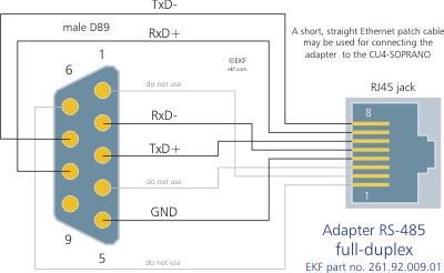
The figure below shows a single rs485 rs422 signal being transmitted. Figure 3 is an rs485 wiring diagram for rs485 pinout db9 connectors.

Cu4 Adp485 Electronic Circuit Projects Dmx Usb
Check the data sheet schematic or block diagram.

485 wiring diagram. If you wish to transmit four signals then eight wires are needed. The recommended arrangement of the wires is as a connected series of point to point nodes a line or bus. The distances these signals are carried is greater due to differential signals.
The complete ethernet pinout cable wiring reference with wiring step by step guide. Two wires are required for each signal. It reveals the parts of the circuit as simplified shapes and the power as well as signal links in between the gadgets.
Rs 2 wire half duplex or rs 4 wire full duplex or rs 4 wire full duplex follow the wiring diagram in figure1 to connect to a 2 wire half duplex. Rs 485 is designed to transmit this information over significant lengths and 1000 meters are well within its capability. Two switches are set for 2w or to the 2 wire rs 485 mode.
Controlsoft recommends using a slot head screwdriver with a blade 3 32 wide suitable for size 0 or 1 screw. Click to find view print and more. Eia 485 cable usually made with twisted pair like eia 422 and may span up to 1200 metres.
Figure 4 is a pin diagram for both 25 pin rs485 pinout half duplex and full duplex pinout connectors. Click to check the right one for you or print as reference. Figure 3 applies to most b b rs 485 converters or serial cards that can be set for 2 wire or 4 wire operation and for some 2 wire converters that use the same circuit board for the rs 422 model.
Rs485 half duplex wiring diagram two wire rs networks operate in half duplex mode on one twisted pair plus a the following diagram shows the daisy chain topology. Rj45 pinout diagram shows wiring for standard t568b t568a and crossover cable. The distance and the data rate with which rs 485 can be successfully used depend a great deal on the wiring of the system.
A wiring diagram is a streamlined traditional pictorial representation of an electric circuit. To transmit a logic 0 line b is low and line a is high. To transmit a logic 1 line b is high and line a is low.
Rs485 and rs422 drive lines in a differential fashion. Ideally the two ends of the cable will have a termination resistor connected across the two wires and two powered resistors to bias the lines apart. The txd and txd lines carry transmit data while the rxd and rxd contain the receive data.
910 series c910 485 controller download specifications nvent raychem c910 485 is a compact single point microprocessor based control and monitoring system for commercial heat tracing applications with integrated ground fault protection. Wiring rs 485 networks to wire the connections carefully strip about 1 4 of the conductor insulation insert the bare conductor into the correct terminal orifice and then fasten the screw. Remember the rj45 wiring order.
Variety of rs485 wiring diagram. Rs 485 is designed to be a balanced system.

405339c07985396d0711d2c2b98714a4 485 583 Cablage Electrique Installation Electrique Maison Cablage Electrique Maison

Figure 2 4 Wire Connections To Radio Modems On Master Side Amp Remote Side Modems Radio Wire

Best Of Wiring Diagram For Light Bar To High Beam Diagrams Digramssample Diagramimages Wiringdiagramsample Wiringdiagram Light Switch Wiring Diagram Relay

5 7 Mercruiser Starter Wiring Diagram Wiring Diagrams With Mercruiser Ignition Wiring Diagram Diagram Wire Ignite

Rs 485 Modbus Serial Communication With Arduino As Master Arduino Arduino Projects Arduino Robot

Wiring Diagram Of Motorcycle Alarm System Bookingritzcarlton Info Wireless Home Security Systems Alarm System Home Security Systems

Image Wiring Diagram Car Horn Relay Wiring Diagram For Horn Relay Explained Wiring Diagrams Car Horn Relay Fire Alarm System Alarm Systems For Home Fire Alarm

Fatek Wiring Diagram Plc Http Bookingritzcarlton Info Fatek Wiring Diagram Plc Diagram Wire Plc Programming

4shared Free File Sharing And Storage Electronics Projects Diy Circuit Converter

Selecting And Using Rs 232 Rs 422 And Rs 485 Serial Data Standards Communication Networks Rs 422 Telemetry

Rs 485 Pinout Tuxotronic Interface Diagram Floor Plans

Unique Circuit Wiring Diagram Wiringdiagram Diagramming Diagramm Visuals Visualisati Electrical Circuit Diagram Electrical Wiring Diagram Circuit Diagram

Wiring Diagram Spy Car Alarm Diagram Diagramtemplate Diagramsample Diagrama De Instalacion Electrica Alarmas Para Autos Simbolos De Electricidad

Cross Platform Rs485 Communication Using Usb2serial Usb To Rs485 Converter Usb Converter Communication

Android Arduino Modbus Over Rs485 Arduino Arduino Projects Diy Arduino Projects

Rs 485 On Rj45 Rj45 Bridal Photography Rs 422

Building Internet Of Things Using Attiny2313 Visit Http Xanthium In Buy Rs485 Modbus Controlled 6 Channel Relay Control Board Wit Relay Arduino Arduino Rs485


