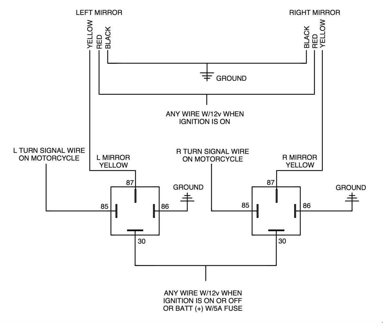
A wiring diagram for a typical turn-signal system is shown in figure 2-69. To get a standard A40 this low youd have to dig a hole to put it in.
Navigation Lights Wiring Diagram Hazard Lights Navigation Lights Turn Ons
Indicator Wiring Diagram Security Indicator Light Circuit.

Indicator Switch Wiring Diagram. Indicator wiring diagram motorcycle. Depending on the position of the turn-signal stalk the power either stops in the switch. 3-way wiring with matching remote switch VP0SR-1L If youre pairing the timer with a matching remote switch youll.
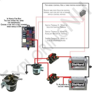
1 Power for the flasher is shifted from Term 15 to 30 which is live all the time. CIRCUIT BREAKER OR FUSE 20A12V IOA24V 12V OR 24V ACTUATOR EXTENSION 7 14 20 26 32 45 Black The keypad cable needs. For wiring a switch you must have these tools and equipment.
This switch also has a built-in LED that lights up when its in the on position so if youve purchased one of these below is a wiring diagram showing how you would go about wiring this particular rocker light switch remember to pay careful attention to the markings on the pins. The black line on the other hand is the hot wire and goes into the hot terminal the one opposite the neutral terminal. In the second case the small bulb contained in the switch.
A Armature No 1 on ignition switch F Field Small terminal on dynamo 4mm wire 25mm wire 4mm wire 25mm wire 25mm wire 674 96AH battery Insulate wires with a good quality insulation tape and place in protective flexible auto wire sleeve MASSEY FERGUSON 35 WIRING DIAGRAM DIESEL 3 CYLINDER WITH DYNAMO GENERATOR. Indicator light wiring diagram. Brother lol there is a light somewhere on the forum there is a diagram of the lines ill see if i can find it.
The power goes through a fuse panel into the thermal flasher. 1 Indicator wiring diagram. Alternately you can wire this directly to a constant power supply from the battery.
From there it goes to the stalk on the steering column. Refer to the wiring diagram in your service manual to identify the indicator wires. Next measure the required length of your wire.
The white wire is the neutral wire and switches into the neutral airport terminal which is marked by silverlight-colored anchoring screws. With wiring diagram motorcycle indicators if you want to secure the incredible images regarding wiring diagram motorcycle indicators click save button to save the shots in your personal computertherere prepared for download if you like and wish to obtain it click save symbol in the post and itll be immediately download in your. If not the structure wont work as it ought to be.
In all cases make sure the control box is mounted with the wires facing down toward the deck. One feed wire to the switch and two wires leading from it to feed the right- and left-hand circuits. Then make sure the wire is connected to the switch.
Im tired of waiting and Im having someone else finish the work. It is not difficult to learn the basic symbols. 2 Multipurpose light switch connections.
12N trailer wiring colour codes for Direction indicator circuit. Each part should be placed and linked to other parts in specific way. Wiring Diagram Turn Signals and Brake Lights wiring diagram is a simplified standard pictorial representation of an electrical circuit.
Yellow 12N plug socket terminal 1. Lets take a look at how the turn-signal circuit is hooked up. Turn signal light dim.
Indicator Switch Wiring Diagram Related Gallery. The turn-signal circuit gets power when the ignition key is on. Trim Tab Indicator Switch w Retractor and Self-Check Wiring Diagram – Part 15070-001 123SC Note.
1 Indicator wiring diagram. Scion OEM style rocker switch wiring diagram. Make sure that you are looking at the wiring diagram that came with your switch and referencing our wiring diagram.
RIGHT TURN INDICATOR FASTEN BELTS INDICATOR BATTERY INDICATOR FEED C250 INSTRUMENT CLUSTER FORD MUSTANG WIRING DIAGRAM FOR 1990-1993 INSTRUMENT CLUSTER C251 INSTRUMENT CLUSTER 90-93 Instrument Cluster Connector Wiring LH Connector C250 Pin 1 LGW – Connect to LEFT on the control box Pin 2 GYW – Connect to HIGH. Basic Car Indicator Wiring Diagram. Garage Door Wiring Electric Connections Cost To Replace Switches And Outlets Fios Wiring Inside House 220 Plug Wiring Diagram For Welder How To Make 1 Phase To 3 Phase 2010 Chevy Impala Fuse Box Diagram Electrical.
The turn-signal switch is located on the steering column fig. Look carefully to make sure none of the wires has fallen off or broken. I have a leviton pilot light switch and the indicator stuning wiring diagram latest wiring diagram for leviton switch diagrams Will the light on the plr come on on the two 3 ways diagram attached when the load is turned from any of.
Turn Signal Flasher Wiring Diagram led turn signal flasher wiring diagram motorcycle turn signal flasher wiring diagram turn signal flasher circuit diagram Every electric arrangement consists of various unique parts. 2 Multipurpose light switch connections. Jeep Wrangler ho gt40p motor w e cam ax15 trans.
May 6 2011 at 427am. American Autowire Universal and Classic Update Kit Bolt On Turn Signal Switch wiring instructionsupdated. A car wiring diagram is a map.
Power to the Switch In the first step the power comes to the switch and then travels to the light. But the Rear Warning Lamp indicator doesnt light. This unit needs to be wired in conjunction with a suitable flasher unit and brake light switch.
From Late 68 thru 71 the 6-wire Turn indicator switch was married to a complicated Hazard switch in order to do away with the expensive 9-terminal flasher. Also note that the polarity of the wiring to the switch is important. Yellow redwhite – main feed.
There are usually three wires attached to the indicator switch. To simplify things cut off the plugssockets leaving the wires protruding from the plastic sheath. With this kind of an illustrative guidebook youll have the ability to troubleshoot stop and total your assignments without difficulty.
LH Turn Signal switch to Left hand direction indicator lamps. RH Turn Signal switch to Right hand direction indicator lamps. 3-way or 2-way.
May 6 2011 at 427am. 12v Relay Switch Wiring Diagram. So my 89 Jeep should have a 4×4 indicator light somewhere.
Typical turn-signal switch. Indicator switch wiring diagram. The composite diagram is shown here.
An installation of a Posi-Lok to cure an ailing 4wd shifting problem. Clipsal Resi Max Residual Cur Circuit Breaker 4p 40 A 30ma Type Ac 415 V. 15 AMP light switch Wire nuts Utility knife Philips screwdriver Wire strippers Needle Nose pliers We will go through the two primary configurations for wiring a light switch.
Class project for today – Adapt the circuit above so it does the same job with only 1 flasher relay like most cars do hint – hazard switches have more than two poles. May 23 2008 at 300pm scaryoldcortina said. Its easy Factory switch Most of you will have a hotrod that uses a steering column that has a turn signal switch built in.
Green 12N plug socket terminal 4. When the switch is pulled Out.

Light Switch Wiring Diagram Basic Electrical Wiring Light Switch Wiring House Wiring

16 Motorcycle Horn Relay Diagram Car Horn Motorcycle Wiring Electrical Diagram

Air Conditioner C S R Wiring Diagram Compressor Start Full Wiring Fully4 Air Conditioner Maintenance Refrigeration And Air Conditioning Hvac Air Conditioning

5 Pin Wiring Diagram Electrical Diagram Electrical Circuit Diagram Trailer Wiring Diagram

Horn Wiring Car Horn Electrical Diagram Diagram

Push Button Ignition Switch Wiring Diagram New Boat Wiring Kill Switch Electrical Wiring Diagram

Unique Wiring Diagram For Chinese 110cc Atv Wiring Diagram Chinese Atv Wiring Diagrams Roketa 11 Motorcycle Wiring Electrical Diagram Electrical Wiring Diagram

Inspirational Wiring Diagram For Rock Lights Diagrams Digramssample Diagramimages Wiringdiagramsample Wiringdia Bar Lighting 12v Led Lights Led Light Bars

30 Beautiful Grote Light Wiring Diagram Circuit Diagram Diagram Turn Ons

Wiring Diagram Ac Generator Valid Modern Dc Wiring Gallery Circuit Diagram Electrical Circuit Diagram Diagram

3 Way Switch Wiring Diagram Light Switch Wiring 3 Way Switch Wiring Electrical Wiring Diagram

12 Motorcycle Led Turn Signal Wiring Diagram Motorcycle Wiring Circuit Diagram Electrical Wiring Diagram

Cat Starter Relay Wiring Diagram Auto Wiring Diagrams Engine Control Unit Automotive Electrical Electrical Wiring Diagram

Installing Turn Signals Motorcycle Wiring Electrical Diagram Electrical Wiring Diagram

Split Ac Full Electric Wiring Diagram Fully4world Fully4world Air Conditioning System Design Refrigeration And Air Conditioning Hvac Air Conditioning

On Off Switch Led Rocker Switch Wiring Diagrams Oznium Boat Wiring Automotive Electrical Automotive Repair

Bosch Relay Wiring Diagram Elegant Electrical Circuit Diagram Circuit Diagram Electrical Diagram

Club Car Turn Signal Wiring Diagram Diagram Turn Ons Electrical Circuit Diagram
Universal Turn Signal Switch Wiring Diagram Wiring Diagram Collection Turn Ons Switch Electrical Projects