Two electric motors one after start up circuit relay control diagram seekic com three phase motor dual sd 2y connection a double y regulation basic variable ac page 4. Single phase motor wiring diagram with capacitor start capacitor run.
Fresh Wiring Diagram Inverter Diagrams Digramssample Diagramimages Wiringdiagramsample Wiringdiagram Thermostat Wiring Ac Wiring Electrical Wiring Diagram
Universal motors have high starting torque can run at high speed and are lightweight and compact.

Two Speed Motor Wiring Diagram. Does switch 2 close at high speed and thus shunt around the triac. DD 1 2 3. In many instances the low- and high-speed coils share an external wire.
This connection is 2 circuits Wye. After the motor has attained a speed of 70 to 80 percent of synchronous the transfer switch operates to change the voltage taps on the transformer. TWO-SPEED MOTORS with 2 separate windings dual winding High speed Red Leads Red Leads Black Leads Black Leads M 3 Single speed only 3Ø WIRING DIAGRAMS U1 – Red V1 – Yellow W1 – Blue Thermal Contacts TB White L1 L2 L3 N E Codes.
HIGH Speed Line 1 to motor terminal 6 Line 2 to motor terminal 4 Line 3 to motor terminal 5 Leave motor terminal 123 open and insulated from each other. Diagram DD6 Diagram DD8 M 1 LN E Diagram DD9 M 1 LN E White Brown Blue L1 L2 N SC Bridge L1 and L2 if speed controller SC is not required Diagram DD7 LN E L1 L2 N SC Z2 U2 Z1 U1 Cap. LOW SPEED Line 1 to motor Terminal 1 Line 2 to motor terminal 2 Line 3 to motor terminal 3 Short circuit motor terminals 45 6 to make the neutral.
Since a two-speed motor relies on different coils to produce different speeds there are usually two input wires. Two-speed Frame Size DT71 thru DV225 Frame Size Low Voltage High Voltage DV200 thru DV225 230V – 60Hz 460V – 60Hz Frame Size Low Voltage High Voltage DT71 thru DV180 230V – 60Hz 460V – 60Hz 200V – 50Hz 400V – 50Hz Frame Size DT71 thru DV132S Frame Size DV132M thru. Below is a wiring diagram for a do it yourself 2 speed switch.
Split Phase Induction. Thermal contacts TB white M 1 Z2 – Yellow AUX. Anybody Here Know Anything About Wiring A Hi-Lo Switch To A 2 in Ao Smith 2 Speed Motor Wiring Diagram image size 720 X 1024 px and to.
2 Speed 230V 56Fr 120A 1110014 Spa Pump Motor 1110014 Spa Pump with Ao Smith 2 Speed Motor Wiring Diagram image size 677 X 548 px and to view image details please click the image. 2 Speeds 1 Direction 3 Phase Motor Power and Control Diagrams. For instance if a module is usually powered up and it sends out a new signal of half the voltage and the technician will not know this he would.
If you are working on two-speed motor wiring you will need an AC power supply the two-speed motor and a double-pole double-throw switch. 22 Less than a minute. In many instances the low- and high-speed coils share an external wire.
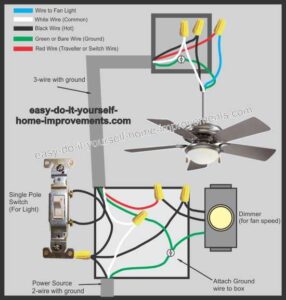
In the above ceiling fan speed control wiring diagram i shown the main winding running winding and i connect run wire of motor to the speed control switch and you can see it in above diagram that connection of run wire of motor in switch L point and and 1 and 2. 3 Phase 2 Speed Motor Wiring Diagram Source. Below is a diagram showing a SPDT center off switch.
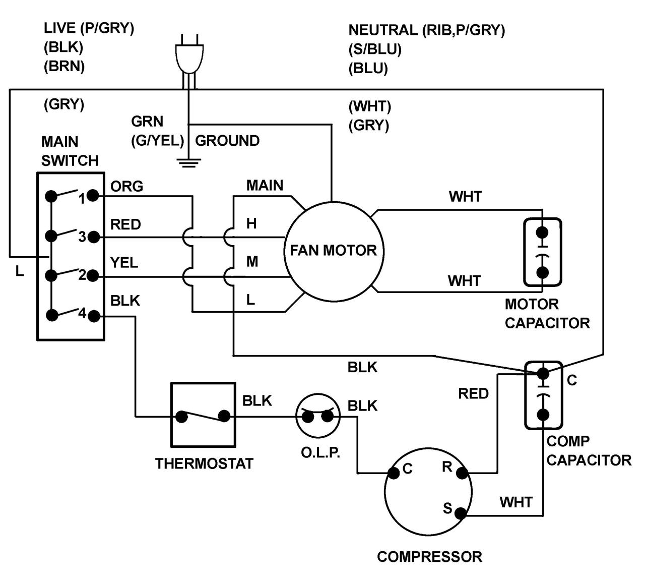
Slow speed as shown in the wiring diagram above and not the fast speed. 2 Speed Fan Motor Wiring Diagram. Single phase 2 speed motor wiring diagram.
609TS is for two-speed separate winding motors only. OL Over Load Relay NO Normally Open NC Normally Close Low Low Speed High High Seed FOR Forward REV Reverse. Checking wires connectors and related components.
Additionally the low speed coil is typically supplied by a red wire while the high speed coil is fed by a black wire. The voltage supplied to the capacitor by means of the transformer can. Terminal markings corresponding to those shown on the diagrams will be found on each switch.
Internal Wiring Diagrams of Small and Fractional Horsepower Electric Motors. Power and control circuit for 3 phase two speed motor. To properly read a electrical wiring diagram one offers to learn how the particular components in the system operate.
2 speed 2 winding motor wiring diagram. Additionally the low-speed coil is typically supplied by a red wire while the high-speed coil is fed by a black wire. 2 Speeds 2 Directions Multispeed 3-phase Motor Power Control Diagram s.
I would like to add a separate switch next to this box bring power into switch. NC Normally Close. Below is the wiring schematic diagram for connecting a SPST toggle switch.
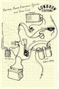
Here is a more complete schematic of your electric drill. Loncin 110cc Wiring Diagram Kuwaitigenius Me Fan Motor Electric Cooling Fan Electric Fan. 2 Speeds 1 Direction 3 Phase Motor Power And Control Diagrams Electrical Circuit Diagram Electrical Diagram Circuit Diagram.
A wiring diagram is a streamlined standard pictorial depiction of an electric circuit. Two-speed electric motors operate in one of two ways. The other terminal is.
Diagram DD5 TWO-SPEED MOTORS For all other SINGLE-PHASE wiring diagrams refer to the manufacturers data on the motor. All circuits are usually the same. 1 terminal is for the input.
Low Low Speed. Is the wiring there two switches in the thing. They are commonly used in portable power.
You can see that a SPST toggle switch only has 2 terminals. Since a two-speed motor relies on different coils to produce different speeds there are usually two input wires. 3 Phase 2 Speed Motor Wiring Diagram Source.
Two speed fan motor wiring diagram wiring diagram is a simplified within acceptable limits pictorial representation of an electrical circuit it shows the components of the circuit as simplified shapes and the capacity and signal associates amid the devices. This Is A Split Phase Capacitor Run Electric Motor Diagram Electric Motor Capacitor Electrical Diagram. Tl Tl Tll Reversing Starter Bulletin 609RS Sizes 0 1 3 Phase 2 Phase 3 Wire Two-Speed Starter Bulletin 609TS Sizes 0 1 3 Phase 2 Phase 3 Wire For separate winding motors.
OL Over Load Relay. If you are working on two-speed motor wiring you will need an AC power supply the two-speed motor and a double-pole double-throw switch. Read electrical wiring diagrams from unfavorable to positive and redraw the signal being a straight collection.
Two Speeds One Direction Three Phase Motor Connection Power and Control Diagrams. Diagram DD4 Low speed Low speed U1 U1 V1 V1 W1 W1 U2 U2 V2 V2 W2 W2 L1 L1 L2 L2 L3 L3 E E High speed Red. Two Speeds Two Directions Multispeed 3.
Voltage ground individual component and switches. Wiring diagram for 2 speed fan motor. NO Normally Open.
The wiring diagram in the manual shows what looks like 4 coils connected in 2 series pairs. This guide will explain how to wire a 2-speed v motor to a Hayward Pro Logic.

Pin On Electrical Technology

16 Motorcycle Horn Relay Diagram Car Horn Motorcycle Wiring Electrical Diagram

Park Switch And Windshield Wiper Wiring Diagram With Washer Relay Coil In Wiring Diagram Wiper Motor Chevy Trucks Electrical Diagram Car Wiper

Installing Turn Signals Motorcycle Wiring Electrical Diagram Electrical Wiring Diagram

Unique Wiring Diagram For Chinese 110cc Atv Wiring Diagram Chinese Atv Wiring Diagrams Roketa 11 Motorcycle Wiring Electrical Diagram Electrical Wiring Diagram

Harley Davidson Wiring Diagram Agnitum Me And At Harley Wiring Diagram Pocket Bike Sportster Home Electrical Wiring

2 Speeds 1 Direction 3 Phase Motor Power And Control Diagrams Electrical Circuit Diagram Electrical Diagram Basic Electrical Wiring

Unique Trane Heat Pump Thermostat Wiring Diagram Thermostat Wiring Electrical Diagram Trane Heat Pump

Unique Single Phase Capacitor Start Capacitor Run Motor Wiring Diagram Electrical Wiring Diagram Electrical Circuit Diagram Capacitor

5 Pin Relay Wiring Diagram Electrical Circuit Diagram Circuit Diagram Electrical Diagram

60 Beautiful Motor Starter Wiring Diagram Electrical Circuit Diagram Circuit Diagram Electrical Wiring Diagram

Horn Wiring Car Horn Electrical Diagram Diagram
2 Speeds 1 Direction 3 Phase Motor Power And Control Diagrams Electrical Circuit Diagram Electrical Diagram Basic Electrical Wiring

Weg Motor Capacitor Wiring Diagrams Schematics And Baldor Diagram In Electric Motor Electrical Wiring Diagram Motor

Single Phase Motor With Capacitor Forward And Reverse Wiring Diagram Circuit Diagram Electrical Circuit Diagram Electrical Diagram

Wiper Switch Wiring Diagram Best Of Diagram Stereo Idea Trailer Wiring Diagram

Inspirational Ge Motor Starter Wiring Diagram Washing Machine Motor Electric Dryers Electrical Diagram

Square D Motor Control Center Wiring Diagram Well Pump Pressure Switch Diagram Wire

Download 28 Wiring Diagram Washing Machine Motor Washing Machine Motor Washing Machine Washing Machine Problems