Most ladder diagrams show the following basic components. And you should select the most appropriate diagram that matches the components you have installed in your system along with what you re hoping to achieve in terms of controllability.
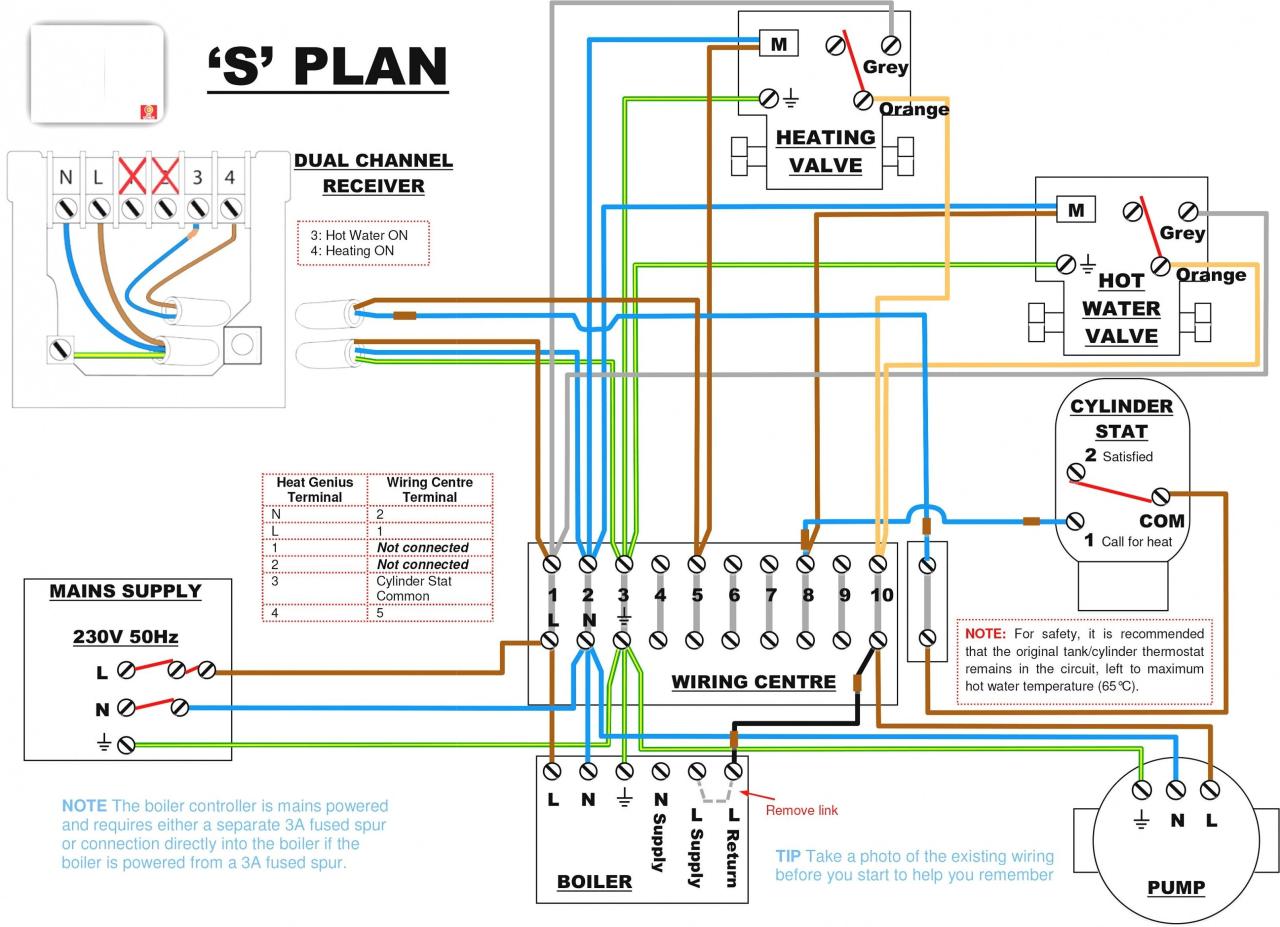
Wiring Diagram For Central Heating System S Plan Diagram Diagramtemplate Diagramsample Central Heating System Heating Thermostat Heating Systems
Air handling unit ahu.

Typical central heating wiring diagram. Heat pumps are different than air conditioners because a heat pump uses the process of refrigeration to heat and cool while an air conditioner uses the process of refrigeration to only cool the central air conditioner will usually be paired with a gas furnace an electric furnace or some other method of heating. It lists the circuit connections and electrical wiring for the system. An air handler is usually a large metal box containing a blower heating or cooling elements filter racks or chambers sound attenuators and dampers.
18 gauge standard single thermostat standard a c condenser ac contactor control board standard air handler 3 this diagram is to be used as reference for the low voltage control wiring of your heating and ac system. The basic heat a c system thermostat typically utilizes only 5 terminals. Thermostat wiring diagrams for heat pumps heat pump thermostat wire diagrams.
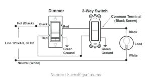
A device used to condition and circulate air as part of a heating ventilating and air conditioning hvac system. There are almost infinite variations but there are four main types. Where the power supply is what path the power takes the load component the switch component and a.
The diagram set includes wiring plans for a number of popular configurations of central heating systems c plan w plan y plan s plan s plan etc. Another hurriedly thrown together page i m afraid people often ask me for central heating diagrams showing how the pipework circuits are arranged in a central heating system. Do it yourself lovers utilize wiring diagrams but they are likewise typical in house structure and also auto repair.
Because it explains electrical circuits the diagram looks like a ladder which is where the name comes from. A home building contractor will desire to validate the physical place of electric outlets as well as light fixtures making use of a wiring diagram to avoid costly errors and constructing code violations. Rc red wire power 24 vac rh or 4 red wire jumpered power 24 vac w white wire for heating enable y yellow wire for cooling enable g green wire controls fan on auto the diagram shows how the wiring works.

Wiring Diagram Intertherm E2eb 012ha Goodman Entrancing Electric Furnace On For Thermostat Wiring Electric Furnace Carrier Furnace

Programmable Thermostat Wiring Diagrams Hvac Control Thermostat Wiring Thermostat Hvac Controls

C Plan Wiring Diagram Central Heating Diagrams To Download Also Remarkable Fire Diagram Proposal

Unique Wiring Diagram For Underfloor Heating Thermostat Diagrams Digramssample Diagramimages Heating Systems Thermostat Wiring Electric Underfloor Heating

Lovely Wiring Diagram For Honeywell S Plan Diagrams Digramssample Diagramimages Wiringdiagramsample W Thermostat Wiring Heating Systems Heating Thermostat

Electrical Wiring Diagrams For Air Conditioning Systems Part Two Electrical Kn Electrical Wiring Diagram Air Conditioning System Electrical Circuit Diagram

Cool Intertherm Thermostat Wiring Schematic Photos Thermostat Wiring Trane Heat Pump Heat Pump

New Wiring Diagram For Sunvic Central Heating Diagram Diagramtemplate Diagramsample

Honeywell Y Plan Diagram Google Search Central Heating System Central Heating Heating Systems

Furnace Wiring Diagram Eb15b Electric Arresting

Electrical Wiring Diagrams For Air Conditioning Systems Part Two Electrical Knowhow Electrical Diagram Air Conditioning System Electrical Wiring Diagram

Wiring Diagram For Central Heating System S Plan Diagram Diagramtemplate Diagramsample Thermostat Wiring Heating Thermostat Electric Underfloor Heating
Simple Danfoss 3 Way Valve Wiring Diagram Uk Diy Faq Electrical And Mid Position Heating Systems Electrical Diagram Central Heating

Unique Wiring Diagram Ac Blower Motor Diagram Diagramtemplate Diagramsample Electrical Circuit Diagram Basic Electrical Wiring Circuit Diagram

Electrical Wiring Diagrams For Air Conditioning Systems Part One Electrical Knowhow Electrical Diagram Air Conditioning System Electrical Wiring Diagram

Danfoss Wiring Diagram Central Heating Diagram Diagramtemplate Diagramsample Central Heating System Heating Thermostat Heating Systems

Unique Honeywell T6360b Room Thermostat Wiring Diagram Diagram Diagramsample Diagramtemplate Wirin Thermostat Wiring Central Heating System Central Heating

New Honeywell Central Heating Thermostat Wiring Diagram Diagram Diagramtemplate Diagramsample Thermostat Wiring Heating Systems Heating Thermostat

Diagram Diagramsample Diagramtemplate Wiringdiagram Diagramchart Worksheet Worksheettemplat Central Heating System Honeywell Thermostats Heating Systems