All other control and power connections have to be made by the installer as per the dotted lines. The star delta y δ 3 phase motor starting method by automatic star delta starter with timer.
Single Phase Starter Connections Circuit Diagram Diagram Single
13 17 with a flying lead to be connected to overload terminal 95.

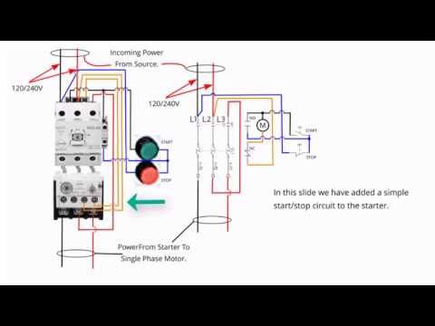
Single phase starter wiring diagram. It uses a contactor an overload relay one auxiliary contact block a normally open start pushbutton a normally closed stop pushbutton and a power supply with a fuse. A wiring diagram is a type of schematic which uses abstract pictorial symbols to demonstrate every one of the interconnections of components inside a system. The above diagram is a complete method of single phase motor wiring with circuit breaker and contactor.
At the bottom of this post is also a video about dc shunt motors. The start and stop circuits could alternatively be controlled using a plc. It reveals the parts of the circuit as simplified shapes and the power and signal links between the gadgets.
Phase 1 l2 l4. I have compiled a group of single phase electric motor wiring diagrams and terminal connections below. Adjoining cable routes might be shown roughly where specific receptacles or fixtures must get on a typical circuit.
Single phase electrical wiring installation in a multi story building three phase electrical wiring installation in a multi storey building. A2 14 18. Full voltage single phase motors this diagram is for single phase motor control.
Literally a circuit is the course that allows power to. The function is the exact same. Text links below go to applicable products on amazon and ebay.
Wellborn collection of single phase motor starter wiring diagram. January 6 2020 by larry a. In the above one phase motor wiring i first connect a 2 pole circuit breaker and after that i connect the supply to motor starter and then i do cont actor coil wiring with normally close push button switch and normally open push button switch and in last i do connection between capacitor.
How to wire a single phase kwh meter digital or analog energy meter from the supply to the main. A wiring diagram is a simplified traditional photographic representation of an electric circuit. Typical controller markings typical elementary diagram iec typical controller markings typical elementary diagram table 4 control and power connections for across the line starters 600 v or less from nema standard ics 2 321a 60 1 phase 2 phase 4 wire 3 phase line markings l1 l2 l1 l3.
Where can i find single phase electric motor wiring diagrams. Single phase submersible pump starter wiring diagram building wiring representations reveal the approximate locations as well as affiliations of receptacles lighting as well as irreversible electric solutions in a building. Phase 2 l1 l2 l3 ground when used.
A very first look at a circuit diagram could be complicated yet if you can read a metro map you can review schematics. Single phase motor starter wiring diagram pdf a novice s overview of circuit diagrams. 1 three phase supply 230volt coil see wiring diagram u.
Obtaining from point a to direct b. Single phase motor starter wiring diagram what s wiring diagram. The following links are pre fitted to the starter.

Single Phase 3 Wire Submersible Pump Control Box Wiring Diagram Submersible Pump Electrical Circuit Diagram Submersible

240v Motor Wiring Diagram Single Phase Collection Single Phase Motor Wiring Diagram With Capacitor Electrical Diagram Electric Motor Electrical Circuit Diagram

Single Phase Submersible Pump Starter Wiring Diagram On Water Control Panel Inside To Submersible Pump Submersible Submersible Well Pump

Great Single Phase Starter Wiring Diagram A Big Compressor Throughout Electrical Wiring Diagram Air Compressor Pressure Switch Circuit Diagram

Single Phase Submersible Pump Starter Wiring Diagram Gooddy Org Best Of Submersible Pump Submersible Submersible Well Pump

Electrical Wiring Single Phase Motor Starter Wiring Diagram Submersible Well P 2 Way Distribution Board Electrical Circuit Diagram Electrical Wiring Diagram

Direct On Line Starter Wiring Diagram Directions Electrical Diagram Dol

Forward And Reverse Motor Starter Wiring Diagram Elec Eng World Electrical Circuit Diagram Circuit Diagram Electrical Diagram

Direct On Line Dol Wiring Diagram For 3 Phase With 110 230vac Control Circuit Electrical Circuit Diagram Circuit Diagram Electrical Wiring Diagram

Shihlin Motor Starter Wiring Diagram Wire Switch Electrical Wiring Power Source

Pin By Brian Jones On Tools In 2020 Line Diagram Electrical Diagram Electricity

Dol Starter Panel Wiring Diagram Save Start Stop And Motor Electrical Circuit Diagram Circuit Diagram Electric Circuit
35 Lovely Square D Manual Motor Starter Wiring Diagram In 2020 Diagram Circuit Diagram Wire

Wiring Diagram For 220 Volt Single Phase Motor Http Bookingritzcarlton Diagrama De Instalacion Electrica Diagrama De Circuito Electrico Diagrama De Circuito

Unique Wiring Diagram Ac Motor Single Phase Diagram Diagramtemplate Diagramsample Electrical Circuit Diagram Circuit Diagram Home Electrical Wiring

Single Phase Submersible Pump Starter Wiring Diagram Wiringdiagram Org

Single Phase Motor Contactor Wiring Diagrams Png 848 632 Electrical Wiring House Wiring Electricity

Wiring Diagram For Motor Starter 3 Phase Controller Failure Relay Electrical Pleasing Instalacion Electrica Industrial Electricidad Industrial Diseno Electrico

Single Phase Dol Starter Dol Starter Connection In Tamil English Youtube Dol Starter Single