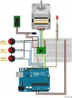
I am not recommending this motor specifically but at least you could follow the same wiring pattern if you use it. Genuine arduino uno 22 95 arduino store.
Come Pilotare Un Motore Passo Passo Con Arduino E Il Driver A4988 Arduino Arduino Projects Arduino Cnc
Use an allen wrench to remove the screws securing your fan.

Cr10s wiring diagram. The cr10s pro rubber feet would still have kept the motor from touching the table top but i didn t want to cut a hole in the case. Now to remove the hotend. In this video we will show you how to check the cr 10 motherboard wiring upgrade package.
4 mount the main fan 2 mount the blower. Cr10s pro wiring help. Make sure the 6 10 pin adapter is facing the correct way as seen.
Thank you for always support and we will continue to improve ple. If you connect your bltouch and when auto homing the sensor doesn t register the z axis keeps dropping pressing into your bed turn your printer off. Disconnect your hotend wiring assembly.
The specific motor i bought was the 17hs19 2004s1 from stepper online. To tension the belt loosen the 4 bolts 2 on each side and pry the bracket assembly away from the print bed just like in the cr 10 assembly video. I find multiple things online and youtube but it doesn t get me close enough.
Cr10s pro wiring help. Creality cr 10 wiring diagram wiring diagram is a simplified all right pictorial representation of an electrical circuit it shows the components of the circuit as simplified shapes and the gift and signal connections amid the devices. If you have the stock fan housing the process is the same.
I bought it on ebay. V2 0 v2 1 board use the same pin out for the bltouch if you have the v2 1 board follow the wiring guide for v2 0. Posted by 1 year ago.
Six screws total two are longer they mounted the hotend itself. Nathan dickman humans do not know the answers to their most important questions. Plug in the usbasp programmers 6 10 pin adapter into the cr10 motherboards as shown below for cr10 or cr10s and plug the programmer into a usb port on your pc.
So the other day i started replacing all fans in my cr10s pro to ulta quite fans and installing inductive bed level sensor but it s been a few daysbsince i started it and took it apart and can t for the life of me find my note of where everything went or. My issue is the thermistor for the bed and nozzle works registering the temps however i can only get one or the other to start heating when i mess around with the wiring but not both. Does anyone have a wiring diagram for the cr10 to cr10s v2 1 motherboard.
Wiring diagram for cr10 non s wiring diagram for cr10 s.
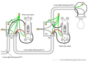
Wiring Diagram For House Lighting Circuit Http Bookingritzcarlton Info Wiring Diagram For House Light Types Of Electrical Wiring Parallel Wiring Electricity

Mosfet Wiring On Anet A8 3d Pechat Elektronika Printer

A Diy Valve Overdrive Pedal Goldie Diy Guitar Pedal Guitar Pedals Guitar Tech

Pin On 3d Printer Enclosure

How To Make Car Led Chasing Tail Light Brake Light Circuit Homemade Circuit Projects Car Led Led Circuit Projects

Bme280 Sensor With Arduino Tutorial Learn Robotics Arduino Learn Robotics Arduino Projects

Cr 10 10s V2 Acrylic Enclosure Case Kit 3d Printer Enclosure 3d Printing Diy 3d Printing

Nachinka Bloka Upravleniya Chpu Plazmoj Cnc Plasma Control Box Guts Cnc Controller Arduino Cnc Cnc

Pin En Things To Make

Let S Code With Stm32 Nucleo Open Development Platform Electronics Infoline Electronics Infoline In 2020 Fpga Board Arduino State Diagram

Upgrade Using An Atx Power Supply With The Cr 10 Atx Upgrade Power Supply

Wire Limit Switches Diy Cnc Router Cnc Controller Diy Cnc

Mg 811 Co2 Gas Sensor Module Sensor Arduino Projects Arduino

Pin On Dfl Srp All In One Usb3 0 Data Recovery Equipment

How To Make Car Led Chasing Tail Light Brake Light Homemade Circuit Projects Circuit Projects Electronic Circuit Projects Car Led

Motorcycle Engine Diagram Engineering Drawings And Drive Motorcycle Engine Diagrams Wiring Diagram Di 2020

Arduino Rc Boat Radio Controlled Boats Rc Boats Boat Wiring

Pin By Steve Sutter On Elettronica Stepper Motor Diy Electronics Electronics Projects

Digital Volume Control Circuit Diagrams Schematics Electronic Projects Electronics Projects Circuit Diagram Wearable Electronics