For additional information and a complete wiring diagram. Emergency Power Off EPO Wallmounted Normally Open NO Switch Can be cascaded with CAT5 cable.
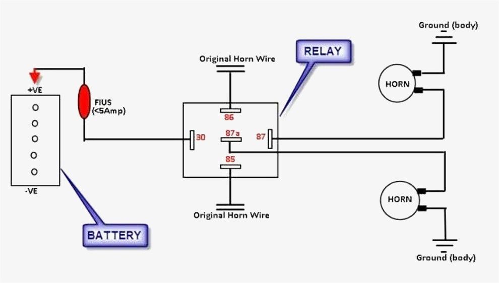
Horn Wiring Car Horn Electricity Horns
All unused control connections must be.

Epo Switch Wiring Diagram. EPO circuits provide a fast simple method of shutting down power to a room or piece of equipment. A complete guide of single phase induction motor wiring connection with magnetic contactor or stater. Iv Emergency Power Off EPO Switch Activated 1 Emergency Power Off EPO switch activation red led is illuminated 2 2nd alarm shutdown relays are energized and latched 3 2nd Alarm momentary 5 seconds 120V shunt trip circuit shall activate 4 All 2nd alarm equipment shall de-energize 5 Discharge shutdown relays are energized and latched.
Diagram wiring diagram for an emergency stop button full version hd quality stop button. Sump pump installation diagram tripwire diagram shunt breaker wiring EPO Switch Wiring DiagramEPO Switch WiringShunt Trip BreakerPlease provide a field wiriing diagram for connecting an EPO in a data center to a Trane Model XXXXX so that the CRAC unit will shut down when the EPO is engaged. By the way the EPO panel and switch are located in two different areas.
Emergency Power-Off Circuits Application Note – AN-16 App Note AN -16 Rev. Referring to Figure 9 use a voltmeter to check for the presence of voltage. Get the 10 gauge wire and place it through the hole in your fire wall.
There should be a wiring diagram glued to the inside of the units electrical control panel however. Apc epo wiring diagram Creative Epo Switch Wiring Diagram APC EPW9 Emergency Power f EPO Switch Bomara Associates. Epo With Two Smoke Detectors And Shunt Trip Breaker Wiring Diagram.
Emergency Power Off EPO is the capability to. Aug 26 2018 Chevrolet 1500 pick up 1995 in the dash electrical circuit wiring diagram chevrolet diesel 3500 1999 electrical circuit wiring. L The schematic or line diagram includes all the components of.
Emergency Power Off Switch POWER NORMAL BYPASS TEST 2 ND ALARM DISCHARGE ACTIVATION EPO OUTPUT Power Equipment Dampers Fans HVAC Block Diagram The integrated EPO controls can be thought of as an Emergency Power Shutdown Management System hereafter referred to as an EPSMS. I am assuming thats how the switch gets wiredto the EPO panel. Shunt breaker wiring diagram Wiring Diagram for Shunt Trip Breaker Copy Best Shunt Trip Breaker Wiring Diagram 71 for Chromalox Heater.
Emergency Stops 4 Section 2 Basic Training Product definition An Emergency Stop is defined as a fail-safe control switch or circuit that when de-energized will stop the operation of associated equipment and will shut off all potential hazards. Shunt Trip Breaker Wiring Diagram with EPO Button. Was not sure about the second rectangle.
Mar 16 2020 Peterbilt 337 Wiring Diagram wiring diagram is a simplified enjoyable pictorial representation of. You can cascade the boxes so that you only wire devices to one box see page 8 or you can wire devices directly to each EPO box see page 10. When the Emergency Power Off Switch is activated all connected 3 2nd Alarm momentary 5 seconds V shunt.
This i When connected to a fire suppression system. 20 1 1995 and 1999 TEAL Electronics Corporation The Emergency Power Off EPO button is a common feature in many medical industrial and data processing facilities. I own a 2004 chevy Colorado.
Wiring Diagram Pics Detail. This is not a short circuit safety switch. The AC Connect Block Cover Plate is located to the right of the Control Panel Cooling Fan on the right side of the unit.
99 Cavalier Venture 2004-2005 CD MP3 radio GM. Electric fan relay wiring diagram wiring diagram is a simplified tolerable pictorial representation of an electrical circuit it shows the components of the circuit as simplified shapes and the capability and signal contacts between the devices. You have two alternatives for wiring your additional EPO boxes.
See also F250 Wiring Diagram Sample. Wiring Diagrams 2 Way Light Switch Lighting Diagram Inside Two. Emergency power off switch wiring diagram.
Typical Wiring Diagrams For Push Button Control Stations 3 Genera Information Each circuit is illustrated with a control circuit continued schematic or line diagram and a control station wiring diagram. If aluminum AC supply wire is. I am assuming thats how the switch gets wiredto the EPO panel.
Typical wiring diagrams for push button control stations 3 genera information each circuit is illustrated with a control circuit continued schematic or line diagram and a control station wiring diagram. Provides a single point of emergency equipment shutdown for up to eight APC InfraStruXure devices and one third-party device. It looks like 120v from panel to EPO panel but would it also be 120v from EPO switch to EPO panel.
Remove the AC Connect Block Cover Plate. Remote Emergency Power Off switch boxes are available to provide access to Emergency Off control in any location and may connect to the Master EPO Control or to any slave via a pass-through control connector. You can route the red wire attached to the 24 volt side of the transformer through your normally closed EPO contacts.
Shunt trip breaker wiring diagram this post is about the single wiring diagram of mccb shunt trip breaker. Epo switch wiring diagram. The controls on all of these units are powered by a 24 volt transformer.
Understanding the Siemens EPO circuit requirements and getting them connected properly the first time Each room with Siemens equipment must have an EPO button. Our EPO stations are guaranteed compatible and come with easy to follow wiring diagrams. It shows the components of the circuit as simplified shapes and the capability and signal links in the middle of the devices.
But those RSa are SQD contacts so I assume LV wiring. 2 Enclosure diagram showing the key switch indicating LEDs and labels. Wiring Diagram for the EPW9.
EPO Emergency Power-off ESS Energy Saver System F-UPM Field Installed UPM IPM Intelligent Power Manager IPP Intelligent Power Protector MBP Maintenance Bypass MBS Maintenance Bypass Switch MCB Miniature Circuit Breaker MIS Maintenance Isolation Switch MOB Module Output Breaker REPO Remote Emergency Power-off RIB Rectifier Input Breaker. When the EPSMS receives a ii EPO Switch. The desired features of a quality EPSMS installation are as.
To mount additional EPO boxes at other exit doors fo llow the instructions in fiMount the system on a wallfl on page 3. Helps limit damage and makes emergency rescue attempts safer. The idea is to remove power in an emergency not to control the onoff power of your load.
You can cascade the boxes so that you only wire devices to one box see page 8 or you can wire devices directly to each EPO box see page 10. To mount additional EPO boxes at other exit doors follow the instructions in Mount the system on a wall on page 3. ABB Training Manual No.
Wiring Diagram Pictures Detail. With just two wire terminals on the 24 volt side. You have two alternatives for wiring your additional EPO boxes.
I could not find this anywhere on line.

Marine Power Inverter Wiring Diagram Trailer Wiring Diagram Diagram Wire

Pin On N

Installing Turn Signals Motorcycle Wiring Electrical Diagram Electrical Wiring Diagram

Wiring Diagram Ac Generator Valid Modern Dc Wiring Gallery Circuit Diagram Electrical Circuit Diagram Diagram

60 Beautiful Motor Starter Wiring Diagram Electrical Circuit Diagram Circuit Diagram Electrical Wiring Diagram

Alternate 4 Way Switch Wiring Diagram Light Switch Wiring 4 Way Light Switch 3 Way Switch Wiring

How To Wire A Shed For Electricity Diagram House Wiring Home Electrical Wiring Electrical Wiring

Wattmeter Connection Diagram And Wiring Connection Electrical Installation Diagram
Best Bosch Relay Wiring Diagram 5 Pole Electrical Outlet Symbol 2018 Electrical Circuit Diagram Light Switch Wiring Electrical Wiring Diagram

55 New Potential Relay Wiring Diagram Electrical Circuit Diagram Ac Capacitor Electrical Diagram

Unique Trane Heat Pump Thermostat Wiring Diagram Thermostat Wiring Electrical Diagram Trane Heat Pump

16 Motorcycle Horn Relay Diagram Car Horn Motorcycle Wiring Electrical Diagram

Bosch Relay Wiring Diagram Elegant Electrical Circuit Diagram Circuit Diagram Electrical Diagram

Ac Wiring Diagram Of Window Airconditioner Ac Wiring Thermostat Wiring Electrical Wiring Diagram

Lewmar Windlass Wiring Diagram Upgrade Windlass Power Wiring Of Lewmar Windlass Wiring Diagram With Windlass Wiring Diagram For Windlas Diagram Power Wire Wire

Push Button Ignition Switch Wiring Diagram New Boat Wiring Kill Switch Electrical Wiring Diagram

Diagram Diagramtemplate Diagramsample Check More At Https Servisi Co Contactor Wiring Diagram Single Phase Diagram Light Switch Wiring Diagram Chart

3 Way Switch Wiring Diagram Variation 3 Electrical Online 3 Way Switch Wiring Three Way Switch Home Electrical Wiring

18 Car Central Lock Wiring Diagram Car Center Electrical Circuit Diagram Car Door Lock