I m using the siemens tia portal as the plc programming software. When the cd diagram includes the plc is still pending.

Plc Panel Wiring Diagram Http Bookingritzcarlton Info Plc Panel Wiring Diagram
So that s what all about programmable logic controller.

Plc control wiring diagram. These look like a normally closed nc contact. All critical safety functions should be hardwired this way. It will be represented with an examine off bit.
Note that these diagrams are without a barrier or isolator fuses and surge protector for keeping it very simple and understandable. Figure 5 below shows a schematic diagram for a plc based motor control system similar to the previous motor control example. It reveals the components of the circuit as streamlined shapes and the power and also signal connections in between the tools.
A wiring diagram is a streamlined conventional pictorial depiction of an electrical circuit. Ina process plant on off control is done through the plc or dcs. A wiring diagram is a simplified conventional photographic representation of an electric circuit.
In this article we are sharing the basic concepts of plc and dcs control systems wiring diagrams for digital input di digital output do analog input ai and analog output ao signals. A controller which can be programmed using various logics. E stop wired cut to power in all devices of the circuit including.
As an introduction to ladder diagrams consider the simple wiring diagram for an electrical circuit in figure 1a the diagram shows the circuit for switching on or off an electric motor. This figure shows that the plc. Plc inputs and outputs plc logic.
This will become clearer when you begin. Assortment of plc panel wiring diagram pdf. Plc training reading electrical wiring diagrams and understanding schematic symbols.
Figure 5 below shows a schematic diagram for a plc based motor control system similar to the previous motor control example. The below figure is an overview of one discrete digital on off circuit showing the entire process from the power. Logic is also required for operation or process.
It shows the elements of the circuit as streamlined shapes as well as the power as well as signal connections in between the tools. Just like on the diagram we start with the stop push button. That s what plc stands for.
But it gets more complicated. To understand how to read ladder wiring diagrams let s start with a simple electrical schematic consisting of a power supply switch and light then you will move on to our control panel sample wiring diagrams. Let s start converting our simple wiring diagram to the plc program in a step by step format.
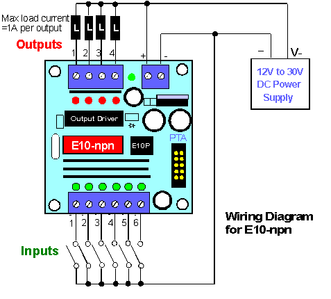
Assortment of plc control panel wiring diagram pdf. Plc wiring diagrams guide include the discrete signals wiring plc digital input modules wiring plc output modules wiring and basics of plc terminations. We are not use only plc wiring.
Figure 5 an electrical schematic with a plc. This figure shows the e stop wired to cutoff power to all of the devices in the circuit including the plc. Types of plc used in industry.
Introduction to plc ladder diagrams.

Plc Panel Wiring Diagram Http Bookingritzcarlton Info Plc Panel Wiring Diagram Electrical Wiring Diagram Circuit Diagram Diagram

Wiring Diagram Plc Omron Http Bookingritzcarlton Info Wiring Diagram Plc Omron Diagram Wire Cool Photos

Wiring Diagram Plc Mitsubishi Http Bookingritzcarlton Info Wiring Diagram Plc Mitsubishi Diagram Electrical Wiring Diagram Circuit Diagram

Wiring Diagram Plc Mitsubishi Http Bookingritzcarlton Info Wiring Diagram Plc Mitsubishi Diagram Electrical Circuit Diagram Electrical Wiring Diagram

Ab Programmable Logic Controller Plc Questions And Answers Suppose We Have An Allen Bra Programmable Logic Controllers This Or That Questions Process Control

Electrical Engineering World Electrical Wiring Diagram Electrical Wiring Electrical Circuit Diagram

Electrical Plc Wiring Diagram On Counters In Ladder Diagrams Ladder Logic Electronic Engineering Plc Programming

Wiring Plc Pengasutan Motor Star Delta Listrik Teknik Listrik Motor Listrik

Plc Programming Questions Answers 3 Instrumentation Tools Plc Programming Ladder Logic Programming

Plc Control Panel Wiring Diagram On Plc Panel Wiring Diagram Electrical Circuit Diagram Electricity Diagram

Plc Program For Forward And Reverse Motor Control Ladder Logic Programmable Logic Controllers Electronic Schematics

Plc Program For Bottle Filling Ladder Logic Ladder Logic Electrical Circuit Diagram Programmable Logic Controllers

Plc Wiring Diagram Guide Ohiorising Org For Motor Control Panel Within Diagram Paneling Control Panels

7 Complex Plc Panel Wiring Diagram Samples Bacamajalah In 2020 Electrical Circuit Diagram Diagram Electrical Panel Wiring

Plc Panel Wiring Diagram Http Bookingritzcarlton Info Plc Panel Wiring Diagram Electrical Circuit Diagram Electrical Wiring Diagram Circuit Diagram

Wiring Diagram Plc Omron Http Bookingritzcarlton Info Wiring Diagram Plc Omron

Plc Ladder Logic Symbols Motor Control Circuits Plc Programming Ladder Logic Electrical Circuit Diagram

Ladder Logic Examples And Plc Programming Examples Ladder Logic Electrical Circuit Diagram Plc Programming

A Plc Has Been Programming To Control The Starting And Stopping Of A Three Phase Electric Motor The Program Plc Programming Ladder Logic Electronic Schematics

