Sw180b 3 Albright 24v Dc Single Acting Solenoid Contactor 150a. How to switch the solenoid valve position from A to B and from B to A with 2 wire 24V adapter 24V and GND.
Ford Solenoid Wiring Diagram Wiring Diagram Blog Ford Mustang Starter Solenoid Wiring Diagram Ford Sol Electrical Wiring Diagram Car Starter Electrical Diagram
The wiring diagram of the solenoid valve is as below.

24v Solenoid Wiring Diagram. What does – mean in wiring diagram. Trolling motor wiring 24 volt starting system on a sport bike schematic battery connections 4 12volt batteries to make volts 24v minkota outdoor gear forum in wire plug elimination 1500 amp series parallel solenoid relay general diagram serial conversion of 12. 12v 24v contactor solenoid.
24 Volt Fuel Shut Off Solenoid Wiring Diagram. Diagram Kubota M4700 Tractor Starter Wiring Diagrams Full Version Hd Quality Wiring Diagrams Meridiandiagram Andreapendibene It. Albright Solenoid Wiring Diagram In addition it will include a picture of a sort that may be observed in the gallery of Albright Solenoid Wiring Diagram.
1224V DC Double Stage 1500 Amp Intermittent duty Cycle 45 Amp Maximum Charge Back Circuit Contacts. The full manual book is here. Circuit Diagram Design Sample Free Download Diagram Diagramtemplate Diagramsample Termostato Termostato Inteligente Aire Acondicionado Split.
24 Volt Dc Reversing Solenoid Continuous Duty Relays T24450 Power. With this kind of an illustrative guidebook you are going to have the ability to troubleshoot avoid and full your tasks easily. 4 pole starter solenoid wiring diagram You will want an extensive skilled and easy to know Wiring Diagram.
4 Pole Starter Solenoid Wiring Diagram. Mayspare continuous duty solenoid relay 24063 24v for golf carts winch marine in rush heavy spst online saint helena ascension and tristan da cunha b07b7flkf1 cole hersee 12 volt 3 terminal copper contact 24106bx solenoids switches circuit breakers electrical misc isolated battery need pos neg earth too doityourself com community forums coleman. Mike Briley from Access Irrigation demonstrates how to wire a 24v irrigation solenoid valve into a mains powered irrigation watering controller using low vol.
12 24 Volt DC Series Parallel Switch 1224 Volt Series Parallel Solenoid Switch Voltage. Trolling Motor Wiring Diagrams. The collection that comprising chosen picture and the.
This solenoid work with 24VDC and have 3 pin wire. In terms of DC attention should be paid to anode and cathode and that the voltage should be the same. Wiring diagram of PLC controlling a 24V solenoid valve via a relay The figure below is a wiring diagram of PLC controlling a 24V solenoid valve with a 24V relay.
With such an illustrative guide you will have the ability to troubleshoot prevent and full your assignments without difficulty. 5 pin is compromised of 3 main pins and an SPDT single pole double throw. John deere 24v to 12v starter conversion kit in kit connect the wires to the starter and solenoid as illustrated on wiring diagram.
24 volt coil solenoid plug wireing Wiring Diagram Line Wiring Diagram Wiring Diagram Line We are make source the schematics wiring diagrams and technical photos. The solenoid is isolated from the. 24v solenoid wiring diagram.
I will never tried to wiring directly without enough information. 8 pin relay how to wire it 08232010 603 am if thats all its powering forget the relay use the dusk till dawn as a. Pin On My Saves.
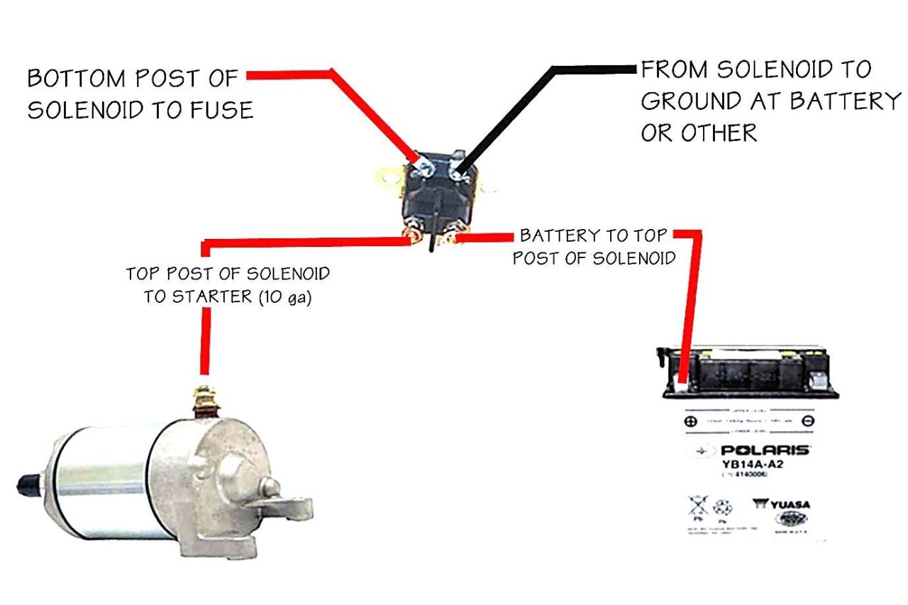
Albright Solenoid Wiring Diagram have an image associated with the other. In terms of AC the anode and cathode cannot be left unconsidered when wiring the solenoid valve. The wiring is not complex and you can wire your motor using the schematics below without a professional.
Then both transistor output and relay output are available. The wiring diagram of the solenoid valve is as below. Solenoid lock with 8 pin connector raceway harness with 8 4 pin connector.
The solenoid switch is composed of a solenoid which is an electromagnetic device that produces the attraction or retention of the moving core. The 24V trolling motor wiring schematic often shows two 12V batteries connected in a series. Silver Flat Base type bracket Large studs.
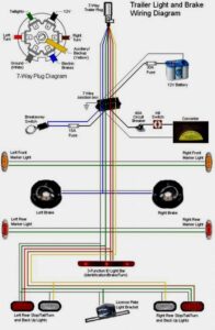
10-32 Studs Typical Wiring Diagram For Negative Ground System. These larger motors and multiple batteries are wired in a series pattern and optimally the circuit breaker should be wired within 4 of. The new solenoid draws only 1 2 watts of power for 12 24v dc and 1 5 watts for 24 120v ac dc 100 240v ac dc.
12 volt relay wiring diagram Youll need a comprehensive skilled and easy to comprehend Wiring Diagram. Both the solenoid and electronic controls. At times the cables will cross.
Connect according to trinary switch wiring diagram. John Deere 24V to 12V Starter Conversion Kit in kit Connect the wires to the starter and solenoid as illustrated on wiring diagram. It shall be noted that if the PLC adopts the transistor output COM of the output point shall be connected to the 0V.
Manual 36542A Solenoid Wiring Instructions Woodward 3 The advantage of using a timer module is that the fuel solenoid pull coil is energized and de-energized by the timer module within approximately 1 second. Find great deals on ebay for 24 volt 8 pin relay. How To Wire Up A 24 Volt Starting System On Sport Bike By.
A wiring diagram is a simplified traditional photographic representation of an electric circuit. April 17 2021 Wiring Diagram. Warn 2500 Atv Winch Wiring Diagram With 62135 B2network Co In Winch Solenoid Winch Electric Winch.
The attached diagram will help with wiring the alternator. John Deere 24 volt problem October 22 AM There is a conversion kit available to swap the 24 volt to a 12 volt system. There is No 1 No 2 and GND pin.
The diagram above is the 5 pin relay wiring diagram. 12 Volt Dc Reversing Solenoid Continuous Duty Relays 12 Volt 24 Volt Dc Power Relays Electronic Circuit Design Relay Electronic Circuit Projects. Connecting two 12V batteries in series provides the 24V power source required to run your motor.
24v flasher circuit diagram electronic unit 6 pin 3 1 flashers and hazards hazard 2 x 21w auto led electronics simplest lamp universal for turn. 24 Volt Wiring Diagram. Image Result For Relay Wiring Diagram.
While small and medium trolling motors use a single 12v marine battery larger trolling motors use larger 24v and 36v systems and require 2 or 3 marine batteries accordingly. In other words the coil of the relay is 24V DC and the contact is 220V AC. Variety of 12 volt solenoid wiring diagram.
Dc Solid State Relay Wiring Diagram Arlyn Scales. 12 24 Volt Dc 1500 Amp Series Parallel Solenoid Relay. To begin wiring at the controller with the power off pull back the outer sheathing exposing the individual wires.

Starter Motor Starting System How It Works Problems Testing Starter Motor Motorcycle Wiring Automotive Repair

Fresh Wiring Diagram Suzuki Quadrunner Diagrams Digramssample Diagramimages Wiringdiagramsample Wiringdiagram Electrical Wiring Diagram Diagram Alternator

Starter Wiring Help Electrical Circuit Diagram Electricity Wire

Fresh Wiring Diagram Inverter Diagrams Digramssample Diagramimages Wiringdiagramsample Wiringdiagram Thermostat Wiring Ac Wiring Electrical Wiring Diagram

Wiring Diagram Ac Generator Valid Modern Dc Wiring Gallery Circuit Diagram Electrical Circuit Diagram Diagram

Horn Wiring Car Horn Electricity Horns

Lewmar Windlass Wiring Diagram Upgrade Windlass Power Wiring Of Lewmar Windlass Wiring Diagram With Windlass Wiring Diagram For Windlas Diagram Power Wire Wire

Cat Starter Relay Wiring Diagram Auto Wiring Diagrams Engine Control Unit Automotive Electrical Electrical Wiring Diagram

Installing Turn Signals Motorcycle Wiring Electrical Diagram Electrical Wiring Diagram

Intertherm Thermostat Wiring Diagram Wiring Forums Diagram Diagram Chart Electrical Wiring Diagram

Ez Go Golf Cart Wiring Diagram Gas Engine Free Wiring Diagram Electrical Wiring Diagram Electrical Diagram Ezgo Golf Cart

Diagram Examples Chanish Org Winch Solenoid Diagram Winch
35 Awesome Ford Starter Relay Wiring Diagram Truck Repair Automotive Mechanic Automotive Repair

Best Relay Wiring Diagram 5 Pin Bosch Electrical Circuit Diagram Circuit Diagram Electrical Diagram

Pin On Diy

Unique Wiring Diagram For Chinese 110cc Atv Wiring Diagram Chinese Atv Wiring Diagrams Roketa 11 Motorcycle Wiring Electrical Diagram Electrical Wiring Diagram

60 New 87a Relay Wiring Diagram Relay Basic Electronic Circuits Electronic Circuit Projects

Push Button Ignition Switch Wiring Diagram New Boat Wiring Kill Switch Electrical Wiring Diagram

Best Bosch Relay Wiring Diagram 5 Pole Electrical Outlet Symbol 2018 Electrical Circuit Diagram Light Switch Wiring Electrical Wiring Diagram