The diagrams below show capacitor connections for typical starting circuits for reduced voltage motor controllers. However some people still struggle with the wiring part of the motor to the capacitor.
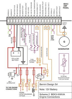
Diesel Generator Control Panel Wiring Diagram Engine Connections Electrical Circuit Diagram Basic Electrical Wiring Electrical Wiring Diagram
How to wire a run capacitor to a motor blowers condensers sometimes when a blower or condenser fan motor goes bad a technician or even a diyer has issues wiring the new motor and capacitor most motors come with clear instructions or a wiring diagram on the side.

Capacitor panel control wiring diagram. George fazio reader contributed comments on failed starter capacitor diagnosis by noting the bulged capacitor ends. 75121 room unit air conditioner wiring diagram sears roebuck window air conditioner wiring diagram for a typical room or window air conditioner. 3 kenmore model 580.
Improper connection may result in damage to the motor and capacitors. Make sure that the circuit matches the actual motor diagram before applying capacitors. A very first take a look at a circuit representation may be complicated however if you can read a metro map you could review schematics.
Below is the circuit diagram of split phase induction motor in a ceiling fan clearly showing a capacitor connected in series with the starting winding auxiliary winding. The aim of project called reactive power compensation panel was to design capacitor bank with rated power of 200kvar and rated voltage of 400v adapted for operation with mains where higher order harmonics are present. Click here to view a capacitor start motor circuit diagram for starting a single phase motor.
Before go in details about why a capacitor is connected in series with the auxiliary winding let is know what will happen if there is no capacitor in a ceiling fan. A wiring diagram is a streamlined standard photographic representation of an electric circuit. Baldor motor capacitor wiring diagram a novice s overview of circuit diagrams.
Learn how a capacitor start induction run motor is capable of producing twice as much torque of a split phase motor. The capacitor bank was to be power capacitor based with automatic control by power factor regulator. Also read about the speed torque characteristics of these motors along with its different types.
Vertical and horizontal lines are used to represent wires and each line represents a single wire that connects between electrical components. Wondering how a capacitor can be used to start a single phase motor. Wiring diagram the wiring diagram is used for the representation of electrical components in their approximate physical location using their specific symbols and their interconnections using lines.
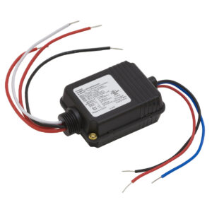
Collection of electric motor capacitor wiring diagram. It shows the components of the circuit as simplified shapes as well as the power and signal connections in between the devices.

Best Of 6 Lead Single Phase Motor Wiring Diagram Diagram Diagram Capacitors Electrical Circuit Diagram

مهندس محمدیان 09132211861 تعمیرات اینورتر اینورتور درایو 3vf Vvvf Vfd Vsd Abb Acs350 Wiring Diagram تعمیر درایو A Circuit Diagram Circuit Diagram

Wiring Diagram Ac Cassette Diagram Diagramtemplate Diagramsample Ac Wiring Electrical Circuit Diagram Electrical Wiring Diagram

Run Capacitor Wiring Diagram Blurts Me Inside Starting

Electrical Panel Board Wiring Diagram Pdf Free Downloads Electronic Circuit Diagram Book Pdf Auto Ele Electrical Panel Wiring Electrical Wiring Diagram Diagram

New Example Plc Wiring Diagram Diagram Electrical Panel Control Panel

55 New Potential Relay Wiring Diagram In 2020 Electrical Circuit Diagram Electrical Wiring Diagram Ac Capacitor

Diesel Generator Control Panel Wiring Diagram Electrical Circuit Diagram Electrical Wiring Diagram Electrical Diagram

Electrical Wiring Diagrams For Air Conditioning Systems Part One Electrical Knowhow Electrical Diagram Air Conditioning System Electrical Wiring Diagram

Electrical Contactor Wiring Diagram Additionally Star Delta Starter Circuit Diagram Together With 2016 Chevy Silverado With Custom Wheels Besi Comandos Eletricos

New Wiring Diagram Garage Door Opener Sensors Diagram Diagramsample Diagramtemplate Wiringdiagram Diagramchar Electrical Wiring Diagram Diagram Alternator

New Wiring Diagram For Ac Compressor Refrigerator Compressor Air Compressor Pressure Switch Exhaust Fan Industrial

Air Conditioner Wiring Diagram Pdf Window Ac Csr Carrier Split In 2020 Ac Wiring Electrical Circuit Diagram Electrical Wiring Diagram

Compressor Start Capacitor Wiring Diagram Diagrams Schematics For Starting Thermostat Wiring Circuit Diagram Ac Wiring

Unique Wiring Diagram Ac Motor Single Phase Diagram Diagramtemplate Diagramsample Electrical Circuit Diagram Circuit Diagram Auto Transformer

Gate1 Ga13 Circuit Board Connections Diagram 40 Access Control Gate Model Operator Sl Electric Gate Motors Sliding Gate Opener Gate Motors

Olympian Generator Wiring Diagram 4001e Collection In 2020 Electrical Circuit Diagram Transfer Switch Electrical Wiring Diagram

Unique Wiring Diagram Of Lg Window Ac Diagram Diagramtemplate Diagramsample Ac Wiring Diagram Circuit Diagram
Ats Panel Genset Controller In Relay Panel Wiring Diagram Electrical Circuit Diagram Circuit Diagram Electrical Diagram