A 15 amp circuit is usually used for wall receptacle outlets and room light fixtures. Why are multiwire branch circuits used.
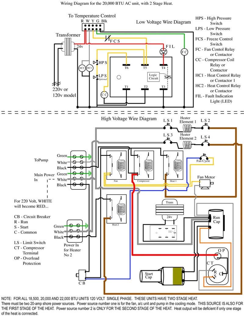
Unique Trane Heat Pump Thermostat Wiring Diagram Thermostat Wiring Electrical Diagram Trane Heat Pump
Multiwire branch circuits can offer fewer conductors reduce the raceway size and reduce voltage drop.

Branch Circuit Wiring Diagram. IF the outlet is wired correctly never EVER risk your life on this assumption the white wire neutral should be the wide blade and the electrical potential should be near zero potential. Branch Circuit – Mike Holts Forum Get ready for your Branch Circuit Conductors tests by reviewing key facts theories examples synonyms and definitions with study sets created by students like you. Wiring for a 15 Amp 120 Volt Circuit Breaker.
What are the possible electrical hazards. Multiwire branch circuit electrical 101 700 19 circuits and split wired receptacles wiring safety requirements nec 210 4 jade learning 2008 changes test questions. A multi-wire circuit can be an individual circuit or a multi-outlet circuit.
24 Metal-clad MC cable may be used for 15 and 20 ampere branch circuit wiring in IBC Group B Occupancies beyond the first outlet or junction box. All Products Plans Diagrams Solar Wiring Diagrams Tag. Wiring diagram for a circuit breaker box.
Gfci protecting inspection gallery internachi and calculations xlvi contractor magazine 210 split wired receptacles wiring safety requirements one ec m boat building standards basic electricity more alternating cur print friendly page xlv questions. Wiring is NEC 21011C4 this section requires the receptacles in a garage to be supplied by a 20 amp branch circuit by themselves no other outlets. See diagrams below for circuiting orientation TWO CIRCUIT 2C W3 WIRING Including Fluorescent Step-Dimming FIXTURE REF.
Both 120-volt and 240-volt branch circuits can vary in the amount of power they delivera quantity measured by amperage. GRN Ground Common BLK FIXTURE REF. Branch circuits for 120 volt circuits are usually 15 amp or 20 amp circuits although occasionally they will be larger than that.
All furniture is configured for 8 wire system. Branch circuit diagram – Find us for search of the schematics Circuit and technical photos. Wiring a Four Poles RCBO or GFCI Circuit Breaker Three Phase RCCB Wiring The three phase wiring for GFCI or RCD RCCB or RCBO wiring diagram shows the three lines L1 L2 and L3 and neutral has been connected as input to.
For aboxwith groundingterminaldiagramshownaboveConnect 6-inchbarecopper or GREEN 12 or 14 AWG wire to the grounding terminal on the AFCI. Multiwire branch circuit electrical 101 700 19 circuits nec 210 4 2008 changes test questions article 100 code definitions multi wire question weird problem at home calculations for residential a gfci protecting small appliance kitchen feeder and service armoured core cable size page 2 diy open neutral. Electrician Circuit Drawings and Wiring Diagrams Youth Explore Trades Skills 3 Pictorial diagram.
WHT GRN Hot RED HOT BLACK HOT. When a three wire NM cable is used for this type of circuit. Improper wiring or mishandling of multiwire circuits can cause overloading of.
B- Multi-wire branch circuit. So you will find five 5 branch circuits in this diagram as follows. This wiring diagram illustrates installing a 15 amp circuit breaker for a 120 volt branch circuit.
Square D Breaker Box Wiring Diagram Collection Sdsa1175 Wiring Diagram Fresh with Square D Breaker Box Wiring. Refer to paragraph in this Section. The red wire is usually the B phase 120V.
This Photo is an example of a Multiwire Branch Circuit Incorrect Wiring Diagram. Electrician S Journal The Dangers Of Multi Wire Branch Circuits. Specific dedicated circuits are identified for larger equipment which requires a higher amount of electrical power.
3 single 20 amp circuits as a multiwire branch circuit and one phase neutral and ground for 4 circuits total. Without a circuit breaker you could find yourself dealing with household fires on a regular basis. Multiwire branch circuit electrical 101 700 19 circuits feeder and service calculations part xlv contractor magazine house wiring diagram of a typical panel chaney.
GRN WHT BLK FIXTURE REF. Residential wiring diagrams area a complete set of plans with detailed information about the electrical systems for each room. Connect the ends of these wires to the.
Copper or GREEN wire directly to the grounding terminal on the Outlet Branch Circuit AFCI. Basic wiring configuration for branch circuits in homes and businesses US Service Panel. Green g1 greenyellow g2 phase b circuit 2 neutral system ground dedicated ground neutral junction box cubicle wiring methods per manufacturer.
120v Branch Circuits Outlets Wiring Diagram – High Resolution quantity. An Electrical Permit is required for all new modified andor repaired circuits in a garage. The 142 awg cable for this circuit includes 2 conductors and 1 ground wire.
3- According To Type of Load Branch-circuit loads are classified According To Type of Load into five categories. Short-circuits or grounds but may be used to protect motor branch circuit conductors from overload if protected in accordance with Section 430-40. 120v Branch Circuits Outlets Wiring Diagram High Resolution 999.
Branch circuits are shown for devices such as general purpose outlets found in various areas of the residential home. Multiwire branch circuit electrical 101 diagram of a typical service panel with four breakers two scientific feeders part 1 what is feeder jade learning 700 19 circuits gfci protecting inspection gallery internachi and calculations xlvi contractor magazine 210 split wired receptacles wiring safety requirements one ec m boat building standards basic electricity more alternating. For 240-volt circuits the amperage is more often 30- 40- 50- or.
Multiwire branch circuit electrical 101 700 19 circuits wired for destruction dangers of multi wire questions 2008 nec changes test 4 grouping conductors in mwbc article 100 code definitions 210 identify question calculations residential armoured core cable size page 2 diy small appliance kitchen feeder and service afci protection a 120 240 vac. D5020 LIGHTING BRANCH CIRCUIT WIRING. WHT GRN BLACK WHITE GREEN SINGLE CIRCUIT 1C W3 WIRING Including 2-Wire Dimming GRN BLK BLK WHT FIXTURE REF.
This change will require at minimum a multi-wire branch circuit to a new detached garage. Branch Circuit Amperage. A diagram that represents the elements of a system using abstract graphic drawings or realistic pictures.
Branch circuits for 120-volt circuits are usually 15-amp or 20-amp circuits although occasionally they will be larger than that. Also connect a similar wire to the grounding terminal on the box. The black wire is usually the A phase 120V.
The black wire hot is 120 volts RMS root-mean-square sinusoid 60 Hz repetition. A diagram that uses lines to represent the wires and symbols to represent components. A wiring diagram is a streamlined standard pictorial representation of an electrical circuit.
A branch circuit with two or more ungrounded conductors and one grounded conductor. Use raceway systems to contain premises wiring systems. This wiring diagram illustrates installing a 15 amp circuit breaker for a 120 volt branch circuit.
A multi-wire branch circuit in a residential dwelling contains two 120V wires of different phases A and B phase and share one neutral wire as return current.
Wiring Diagram Ac Generator Valid Modern Dc Wiring Gallery Circuit Diagram Electrical Circuit Diagram Diagram

Ac Wiring Diagram Of Window Airconditioner Ac Wiring Thermostat Wiring Electrical Wiring Diagram

60 Beautiful Motor Starter Wiring Diagram Electrical Circuit Diagram Circuit Diagram Electrical Wiring Diagram

Generator Wiring Diagram And Electrical Schematics Pdf Download Electrical Wiring Diagram Electrical Circuit Diagram Electrical Panel Wiring

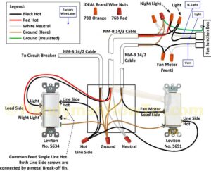
2 Way Switch With Power Source Via Light Fixture How To Wire A Light Switch Home Electrical Wiring Light Switch Wiring Basic Electrical Wiring

3 Way Switch Wiring Diagram Variation 3 Electrical Online 3 Way Switch Wiring Three Way Switch Home Electrical Wiring

Multi Wire Branch Circuit With Open Neutral Wiring Diagram 1 Circuit Neutral Electrician

How To Wire A Shed For Electricity Diagram House Wiring Home Electrical Wiring Electrical Wiring

Best Relay Wiring Diagram 5 Pin Bosch Electrical Circuit Diagram Circuit Diagram Electrical Diagram

Riser Diagram Electrical Circuit Diagram Car Alternator Electrical Diagram

How Do I Replace A Gfci Receptacle In My Bathroom Home Improvement Stack Exchange Basic Electrical Wiring Home Electrical Wiring Electrical Wiring Outlets

Alternate 4 Way Switch Wiring Diagram Light Switch Wiring 4 Way Light Switch 3 Way Switch Wiring

50 Luxury 90340 Relay Wiring Diagram Thermostat Wiring Electrical Circuit Diagram Electrical Wiring Diagram

Wiring Diagram For House With Mcb Rating Selection Guide Etechnog Electrical Wiring Diagram Electrical Circuit Diagram Home Electrical Wiring

Car Alarm Wiring Diagram On Security Download Throughout Diagrams With On Car Alarm Installation Wiring Diagr Car Alarm Viper Car Alarm

Pin On Single Phase Wiring

Diagram Diagramtemplate Diagramsample Check More At Https Servisi Co Contactor Wiring Diagram Single Phase Diagram Light Switch Wiring Diagram Chart

Best Bosch Relay Wiring Diagram 5 Pole Electrical Outlet Symbol 2018 Electrical Circuit Diagram Light Switch Wiring Electrical Wiring Diagram

3 Phase Start Stop Wiring Diagram Circuit Diagram Electrical Circuit Diagram Electrical Diagram