The Type E electrical plug is identified by two round pins spaced 19mm apart with a hole for the sockets male grounding pin. The Electrical Calc Elite is designed to solve many of your common code-based electrical calculations like wire sizes voltage drop conduit sizing etc.

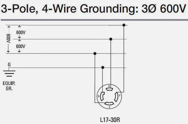
Portal News M 3 Jenis 600 Volt Di Hook Up Kawat Home Electrical Wiring Electrical Circuit Diagram Electrical Engineering Books
Here we also tell you the connection of indicator lamp with electric bell.

Electrical outlet connection diagram. This electrical floot plan sample shows the Power socket outlet layout. For help understanding them be sure to open the Explanation page. Once the electrical project is completed the diagram will be useful for testing and troubleshooting the circuit.
Wiring electrical outlets properly called receptacles and switches involve many of the same basic techniquesMaking safe long-lasting connections requires properly preparing the circuit wires that will connect to the device and securing each wire to the correct terminal. This is a newer version of the outdated 30 amp receptacle appearing in the previous diagram. Sep 28 2018 – how to wire Multiple Outlet In Parallel electrical Wiring Diagram.
The kitchen electric range may also be found to have a 3-wire or 4-wire cord or 220 volt outlet which will require proper electrical connections and wiring as. Touch device users explore by. Electrical circuit diagrams Schematics Electrical Wiring Circuit schematics Digital circuits Wiring.
Convert Cubicle Power Whip To 3 Prong Outlet Electrical Diy inside 3 Prong Plug Wiring Diagram image size 800 X 402 px and to view image details please click the image. So we attempted to get some good 3 prong plug wiring diagram picture for you. Outlet Wiring for a Table Lamp or a Floor Light Fixture.
In this post Electric Bell Connection Diagram we have told you how we can make an electric bell connection. These electrical wiring diagrams show typical connections. The following house electrical wiring diagrams will show almost all the kinds of electrical wiring connections that serve the functions you need at a variety of outlet light and switch boxes.
When wired in parallel as shown in the photo above should an individual electrical receptacle or outlet fail or lose one of its connections such that it loses power the rest of the circuit remains live. When autocomplete results are available use up and down arrows to review and enter to select. The diagram below shows the power entering the circuit at the grounded outlet box location then sending power up to the switch and a switched leg back down to the outlet.
Information on the Type E French 2-pin Electrical Adapter Plug and Electrical Outlet. It gives you over 200 diagrams. Typical connection methods for an electrical outlet or receptacle.
This receptacle has a ground connection not found in the older 30. Wiring Diagram for Dual Outlets. Rewire the Existing Electrical Outlet.
Also here you will see a connection diagram in. Here 3-wire cable is run from a double-pole circuit breaker providing an independent 120 volts to two sets of multiple outlets. Electrical Outlet NEC is also known as Receptacle and more commonly a Socket Outlet IEC.
Outlet Wiring Diagram – pdf 22kb Back to Wiring Diagrams Home. Connect the wires of the new cable to the existing wires. According to NEC an outlet is the points in an electrical wiring system where current can be taken and utilize by electrical appliances and equipment by plugging them in it.
Making electrical connections to a device in an electrical box is easy if there is only one cable entering the boxyou simply attach each circuit wire to a corresponding screw terminal on the device. Run the new cable with sheathing at least two inches up inside the box and double over the. How to wire an electrical outlet wiring diagram Wiring an electrical outlet receptacle is quite an easy jobIf you are fixing more than one outlet the wiring can be done in parallel or in series.
The normal technical term in both British and International English for an AC power socket is socket-outlet but in non-technical common use a number of other terms are used. Directory of Wiring Diagrams. The neutral wire from the circuit is shared by both sets.
Wiring Connections for Receptacles in Parallel. STEPS TO TAKE WHEN WIRING THE ELECTRICAL OUTLETRECEPTACLE. Wiring Diagram for a 30-Amp Dryer Outlet.
Electrical power is thus retained at all of the other receptacles on the circuit. Sep 28 2018 – how to wire Multiple Outlet In Parallel electrical Wiring Diagram. Wiring Diagrams for Switches.
The term plug is in general and technical use in all forms of English common alternatives being power plug electric plug and in the UK plug top. Strip about 10 inches of plastic sheathing from the new cable to expose the black white and copper wires. But it is more complicated if the device needs to be.
Type E outlets will also accept Type C plugs and Type E plugs will also work in Type F outlets. All Circuit Diagram Electrical Circuit Diagram. House Electrical Plan Software for creating great-looking home floor electrical plan using professional electrical symbols.
This wiring is commonly used in a 20 amp kitchen circuit where two appliance feeds are needed such as for a refrigerator and a microwave in the same location. You can use many of built-in templates electrical symbols and electical schemes examples of our House Electrical Diagram Software. Click the icons below to get our NEC compliant Electrical Calc Elite or Electric Toolkit available for Android and iOS.
Actually we also have been noticed that 3 prong plug wiring diagram is being one of the most popular topic right now. Here is a typical connection wiring diagram for a switch device and outlet box connections. Always reference the wiring diagrams listed here to see how the grounding connections should be made both to the outlet box and to the devices.
ConceptDraw is a fast way to draw. Pigtail connections are very handy if you have to connect multiple circuit wires to a device such as an outlet receptacle or light fixture. This circuit is used for a new clothes dryer outlet installation.

Split Plug Wiring Diagram Home Electrical Wiring Basic Electrical Wiring Electrical Wiring

Wiring Diagrams For Electrical Receptacle Outlets Outlet Wiring Wiring A Plug Home Electrical Wiring

Split Plug Wiring Diagram Outlet Wiring House Wiring Home Electrical Wiring

Wiring Diagrams Multiple Receptacle Outlets Home Electrical Wiring Diy Electrical Outlet Wiring

Wiring Diagrams For Multiple Receptacle Outlets Home Electrical Wiring Electrical Wiring Electrical Projects

A Typical Mains Power Plug Electrical Wiring Colours Electrical Plug Wiring Electrical Wiring Diagram

Wiring Diagrams For Electrical Receptacle Outlets Outlet Wiring Wiring A Plug Home Electrical Wiring

Wiring Diagram For House Outlets Bookingritzcarlton Info Home Electrical Wiring Diagram Electrical Wiring

Socket Outlet Wiring Amazing Procedure What Is Socket Outlet Socket Outlet Is A Device With Protected Cu Outlet Wiring Electrical Plug Wiring Wiring A Plug

Pin By Servalo On Electrical Wiring Electrical Wiring House Wiring Electric House

Simple Home Electrical Wiring Diagrams Electrical Wiring Diagram Home Electrical Wiring Outlet Wiring

3 Pin Plug Connections Electrical Engineering Books Electrical Engineering Books Electrical Plug Wiring Plugs

Outlets On Same Circuit Diagram Electrical Wiring Outlet Wiring Gfci

Wiring Diagram For House Outlets Bookingritzcarlton Info Installing Electrical Outlet Basic Electrical Wiring Home Electrical Wiring

Wiring Diagrams For Electrical Receptacle Outlets Electrical Wiring Outlet Wiring Home Electrical Wiring

How To Install Electrical Outlets In The Kitchen Installing Electrical Outlet Home Electrical Wiring Electrical Outlets

Wall Outlet Wiring Diagram Outlet Wiring Electrical Wiring Outlets Home Electrical Wiring

Understanding 240v Ac Power For Heavy Duty Power Tools Make Outlet Wiring Electrical Plug Wiring Electrical Circuit Diagram

Pin By Rafael Urey On How To Wire An Outlet Wiring Diagram Electrical Wiring Outlet Wiring Basic Electrical Wiring

