Dpdt relay wiring diagram this is the diagram below to learn all the pin terminals of a double pole double throw dpdt relay. A DPDT switch can be a bit confusing.
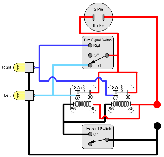
Installing Turn Signals Motorcycle Wiring Electrical Diagram Electrical Wiring Diagram
A Double Pole Double Throw Switch is actually two single pole double throw SPDT switches.

Spdt Switch Wiring Diagram. Single Pole Double Throw relay or SPDT. Mainly it is used in three-way circuit to turn ONOFF an electrical appliance from two location. Spdt toggle switch wiring diagram Led Rocker Wiring Diagram New Toggle Switch.
In each switch lug 2 is common. Panel mount switches come in all sorts of termination styles. Look at the figure 12 the centre dotted line indicates that the DPDT switch is actually two SPDT switches in one package.
Wiring is dead simple. This is the diagram below to learn all the pin terminals of a Single Pole Double Throw SPDT Relay. Single Pole Double Throw SPDT Relay Wiring Diagram.
Lugs 1 and 3 are the two states of the switch. Wiring Diagram Sheets Detail. Fig2 Fig2 shows the 3PDT as three independent SPDT switches.
12 5 Pin Horn Relay Wiring Diagram. Below is the schematic diagram of the wiring for connecting a SPDT toggle switch. You can see the SPDT limit switch has a total of three terminals – Common Normally ClosedNC and Normally OpenNO.
We will now go over the wiring diagram of a SPDT Toggle Switch. One can be Normally Closed and the other one is opened or it can be Normally Open and the other one closed. Here is a diagram.
A SPDT toggle switch has 3 terminals. Below is the schematic diagram of the wiring for connecting a SPDT toggle switch. The polarity of the voltage does not matter.
Wiring Diagram Sheets Detail. What do SPST SPDT DPST and DPDT mean. Spdt rocker switch wiring diagram wiring diagram name can a rocker switch with two positions be an spdt electrical.
3 and 4 connect to the power source. And terminal 3 can connect to any load to power any device. See also Ge Dryer Start Switch Wiring Diagram Sample.
Terminal 2 is the terminal which receives the power necessary so that the loads. A DPDT switch has six terminals. This switch helps you control motor loads.
Place the relays rated coil voltage on these terminals. They are mechanically coupled to control different circuits at the same. Pole refers to the number of circuits controlled by the switch.
A relay consists of two circuits a coil and high amperage circuit. You can observe in the schematic. With just a few small jumpers our switch selection can be used for a multitude of different functions.
A circuit diagram with an LED resistor and a switch. Single-Pole SP Double-Pole DP Switch Wiring Diagrams Diagrams represent both momentary contact or maintained contact switches. The Single Pole Double Throw SPDT relay is quite useful in certain applications because of its internal configuration.
A Double Pole Double Throw toggle switch is a combination of two individual SPDT Single Pole Double Throw switches connected in the single assembly. The pads labels match up to every Aion PCB project so you can run the wires straight across and be done with it. 3PDT Stomp Switch Instructions Refer to diagram 3 to wire a single color LED and diagram 4 for a 2-color 3-lead LED.
Terminal 2 is the terminal which receives the power necessary so that the loads. It shows the components of the circuit as simplified shapes and the knack and signal contacts amid the devices. A relay is an electromagnetic switch used to control multiple circuits by using a single trigger.
Wiring diagram for double pole single throw switch. They can connect two different power sources to two different loads or accessories at the same time. 12v spdt relay wiring diagram.
When the lever of the switch is not pressed the NC terminal is connected to the common terminal but when the lever of the switch is pressed the NC terminal is disconnected from the common terminal and the NO terminal will connect to the common. Below is the schematic diagram of the wiring for. Spdt Relay Wiring Diagram Wiring Diagrams Click 12 Volt Relay Wiring Diagram.
PTH SMD or heavy-duty solder lugs for soldering to wires. Find The BestTemplates at vincegray2014. Each SPDT switch is represented by columns A B and C.
Therefore we get two outputs one from COM and A and second is from COM and B but only one at a time. So basically you can see the SPDT relay as a way of switching between 2 circuits. Spdt Switch Diagram Free Download 2022 by admin.
READ Turn Signal Switch Wiring Diagram Collection. Terminal 1 can connect up to any load to power a certain device. 1 2 5 and 6 are for the loadsaccessories.
13 Spdt Switch Wiring Diagram. SPDT Toggle Switch is a three terminal switch only one is used as input other two are as output. An SPDT switch circuit symbol and an SPDT slide switch.
The Bosch 5 pin relay is a SPDT Single Pole Double Throw switch. While most electronic switches operate on 3 wires UEs Excela is the industrys first 2 wire SPDT electronic switch. The wiring configurations above applies for all SPDT mechanical and electronic switches.
And terminal 3 can connect to any load to power any device. Each component should be placed and connected with other parts in particular manner. It might be easiest to consider it to be two SPDT switches in one.
Relay is a electro-mechanical switch used to control high power application through low power signal electronic circuits for an example a simple timer circuit working under 5V DC bias can. 40 30 Amp Waterproof Relay Switch Harness Set 12v Dc 5 Pin Spdt Automotive Relays 12 Awg Hot Wires Walmart Com Led Store Electrical Wiring Diagram Relay. And terminal 3 can connect to any load to power any device.
DP switches control two independent circuits and act like two identical switches that are mechanically linked. The 2 wires from your SPDT switch terminals can be mapped over to the Excela switch terminals exactly. Spdt rocker switch wiring diagram ON OFF Backlit Rocker Switch Blue LED New Wire Marine And Carling 10.
Terminal 1 can connect up to any load to power a certain device. First of all you should know the relay terminals and wiring diagram before understanding the single pole and double pole relay. A wiring diagram is a.
A SPDT toggle switch has 3 terminals. Switches with Two Pilot Lights SPST Off-On Dependent Independent Four terminals SPDT On-Off-On of On-On dependent Four terminals SPDT On-Off-On or On-On Independent Four terminals Diagram H Diagram J. Wiring Diagram comes with a number of easy to follow Wiring Diagram Guidelines.
Terminal 2 is the terminal which receives the power necessary so that the loads. SP and DP refer to single pole and double pole ST and DT refer to single throw and double throw. It has one common terminal and 2 contacts in 2 different configurations.
SP switches control only one electrical circuit. Wiring polarity does not matter. The 2 COIL terminals is where the voltage is placed in order to energize the coil.
Relays shown in these diagrams can provide options for useful features such as an ac override on and or manual override on. 3PDT is nothing more than three SPDT switches sandwiched together. In other words in one state the foot-switch connects lug2 to lug1.
The first way of wiring uses a couple of Two-Way Light Switches with a three wire control 3 Wire Control.

Push Button Ignition Switch Wiring Diagram New Boat Wiring Kill Switch Electrical Wiring Diagram

16 Motorcycle Horn Relay Diagram Car Horn Motorcycle Wiring Electrical Diagram

Wiring Diagram For Two Switches Controlling Two Lights Light Switch Wiring Home Electrical Wiring 3 Way Switch Wiring

On Off Switch Led Rocker Switch Wiring Diagrams Oznium Boat Wiring Automotive Electrical Automotive Repair

Installation Of Single Pole 3 Way 4 Way Switches Wiring Diagram Electrical Wiring Home Electrical Wiring Electrical Switch Wiring

Horn Wiring Car Horn Electricity Horns

Bosch Relay Wiring Diagram Elegant Electrical Circuit Diagram Circuit Diagram Electrical Diagram

Lewmar Windlass Wiring Diagram Upgrade Windlass Power Wiring Of Lewmar Windlass Wiring Diagram With Windlass Wiring Diagram For Windlas Diagram Power Wire Wire

Best Bosch Relay Wiring Diagram 5 Pole Electrical Outlet Symbol 2018 Electrical Circuit Diagram Light Switch Wiring Electrical Wiring Diagram

Power Window Wiring Diagram Trailer Wiring Diagram Automotive Electrical Motorcycle Wiring

How To Wire A Solenoid Switch Turnout Machine Using A Momentary Spdt Toggle Switch Toggle Switch Diagram Wire

Daylight Running Lights Wiring Diagram Diagram Running Lights Daylight

60 New 87a Relay Wiring Diagram Relay Basic Electronic Circuits Electronic Circuit Projects

Wiring Diagram Ac Generator Valid Modern Dc Wiring Gallery Circuit Diagram Electrical Circuit Diagram Diagram

Light Switch Wiring Diagram Basic Electrical Wiring Light Switch Wiring House Wiring

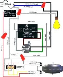
Air Conditioner C S R Wiring Diagram Compressor Start Full Wiring Fully4 Air Conditioner Maintenance Refrigeration And Air Conditioning Hvac Air Conditioning

Wiper Switch Wiring Diagram Best Of Diagram Stereo Idea Trailer Wiring Diagram
Unique Wiring Diagram For Chinese 110cc Atv Wiring Diagram Chinese Atv Wiring Diagrams Roketa 11 Motorcycle Wiring Electrical Diagram Electrical Wiring Diagram

New Wiring Diagram For Light Switch Diagram Wiringdiagram Diagramming Diagramm Visuals Visualisation Light Switch Wiring Electrical Switch Wiring Diagram