For service and for parts for the HD-73. The GOOD news is that Norms Rotor Service has bought all parts all materials and all technical data from Alliance.
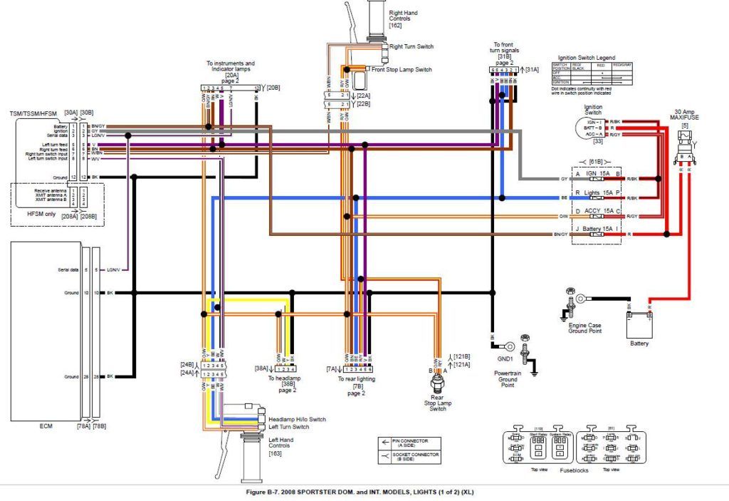
Harley Davidson Wiring Diagram Agnitum Me And At Harley Wiring Diagram Pocket Bike Sportster Home Electrical Wiring
I do not have the controller but I do remember the controller he had was the one with the N E S W N lettering on the face and the long white button on the top of the unit.

Alliance Tenna Rotor Wiring Diagram. Antenna Hdtv Dtv Analog Wiring Tv. Rotator Motor Drive Unit 3. Yaesu g 400 antenna rotator controller programmable vintage alliance model u 100 tenna circuit diagram cde rotor system quick n3ujj just in time m2 orion 2800 repair radio shack control box qrz forums 15 1245 outdoor rca vh126n e45 pine mountain lake airport webcam brake delay for ham m 4 rotators nuts volts magazine.
This assemble the rotor and antenna on ground and then mount to the roof or tower. The unit operates at a speed of one 1. 6 STEP 2 TEM INAL COVER.
We service stock and provide parts for top quality AMERICAN-MADE antenna. Tems and Tenna-Rotor TVs better color getter. I just have the rotor itself.
ALLIANCE is out of the rotor business completely. Antenna Rotor Wiring Diagram Wiring Diagram Line Wiring Diagram. STEP 4 SLIDE TERMINAL COVER UP CABLE AND FASTEN OVER TERMINALS AS SHOWN.
Modern plastics no bakelite or catalin shape. 26506 923 3 in 4 26 60 ALLIANCE MANUFACTURING CO 3329945 3667024 62 66 X8906-B SS ptd. Control Case X-22598-B W-19400-R.
The bad news is. The motor is a 2-phases AC type always. My rotor has 3 only wiring terminals and it.
The theory of operation concerns two separate circuits. I came across an old Alliance Tenna Rotor possibly T-45. The dial of the control box lights when the.
STEP 6 CLAMP ROTOR ON MAST STEP ATTACH SET SCREW AND NUT T O CLAMP PLATE. Alliance Laundry Systems is not responsible for personal injury or property damage resulting from improper service. This change makes possible better orientation for color and black and white television reception improves torque.
I found it on the ground under the antenna in 2 pieces. The rotor unit which mounts on the mast below the antenna and the control box which is placed on or about the TV receiver. Z-19405-B W-22500-R If short any items or if there is hidden damage resulting from rough handling in transportation contact your dealer immediately.
ROTOR INSTALLATION STEP 1 Remove the terminal cover from parts bag. Assistance will be required. Alliance tenna rotor wiring diagram.
Tablemodel low profile big size. Of wires 4 or 5 and the limit-switch or the potentiometer. Controller one part of the dial is under spring tension and a solenoid that.
The unit operates at a speed of one 1. WIRING DIAGRAM The 3005190 a. Antenna Rotator – Tenna-Rotor T-45 – Alliance Manufacturing Co.
Four Mast Support Brackets 4. Control and feedback is about as simple as it gets with a motor turning the antenna mast and a solenoid in the control box that advances the dial as the antenna rotates. Alliance_Tenna-rotor_HD-73-1_userpdf Alliance_Tenna-rotor_HD-73_userpdf Alliance_Tenna-rotor_U-100_servpdf Alliance_Tenna-rotor_U-100_userpdf Alliance_Tenna-rotor_U-110_userpdf Alliance_Tenna-rotor_servpdf Alliance_Tenna-rotor_serv_updatepdf Altron_Lattice_tower_userpdf Altron_winches_brochpdf.
These are interconnected by a four- or five-conductor cable. 4 conductor cable connected to control and rotor. Schematic Wiring Diagram Model U-IOO.
It just slips over the upper pipe piece externally on top of rotor and is tapered to shed water. Tenna-rotor u-83 Tenna-rotor k-22 Tenna-rotor u-98 Tenna-rotor t-20 Tenna-rotor k-22a Tenna-rotor u-100 Tenna-rotor t. Tablemodel with any shape – general.
When you move the knob on the. Dimensions WHD 65 x 475 x 375 inch 165 x 121 x 95 mm. The U-83 U-98 and U-100 controls are protected by a thermostat within the rotor or control assembly.
Source of data collector info sammler. These are interconnected by a four- or five-conductor cable. It belonged to my grandfather years ago before I moved in.
Cams on both ends open and close contacts as required. Tenna-Rotor T-10 antenna pdf manual download. G 400 antenna rotator controller under repository circuits 49394 next gr digiwave ar 500 plus programmable vintage alliance model u 100 tenna rotor installation kirt s cogitation 301 rf cafe two control circuit diagram seekic com interfacing a microcontroller arduino to cde.
It changes for the no. Need to build control box for Alliance Tenna Rotor. Mechanically when rotation is complete.
Tenna-Rotor U-100 – Alliance Manufacturing Co. The Alliance Tenna-Rotor consists of two units. The first is the power circuit which in all Tenna-Rotors transmits the power that.
NRS now owns all rights to and a complete parts inventory for the HD-73 and U100U110 series rotors and control boxes. The dial lights up when the direction is selected and turns off when the antenna reaches that position. The rotor unit which mounts on the mast below the Antenna and the control box which is placed on or about the TV receiver.
View and Download ALLIANCE Tenna-Rotor T-10 service manual online. Locked RotorIOO feet of AWG. The theory of operation concerns two separate circuits.
Unlike the newer systems that use a 3-wire control interface the Alliance U100 TennaRotor uses a 4-wire cable. The alliance tenna rotor u is a fully automatic unit. By Floyd Sens Thu 03 Feb 2005 221513.
Terminal Terminal Terminal Terminal Terminal 20 VAC 18 VAC 15 VAC 20 VAC 17 VAC With rotor turning counterclockwise a pulsing reading of 20 to 25 volts will be read between terminals 1 and 4. Feed the 4-conductor rotor wire through slots of ter minal cover as shown in FIG. Indoor control unit with compass dial.
The rotor case is almost the same for all the models. The Alliance Tenna Rotor U is a fully automatic unit. The first is the power circuit which in all Tenna-Rotors transmits the power that.
The Alliance Tenna-Rotor consists of two units. 5 thoughts on alliance hd73 wiring diagram. It changes for the No.
Has been dedicated to serving all of your rotator needs longer than any current rotator service facility or rotator manufacturer in North America. Need Rubber Seal for ALLIANCE TENNA-ROTOR On top of my Aliance Tenna-Rotor tv antenna rotor there used to be a rubber seal to keep water out of the motor. The Alliance Tenna-Rotor Models K-22 T-12 and U-98 produced after June 1 1958 have been changed from a speed of 2 RPM to a speed of 1 RPM.
HD-73-1 CARTON CONTENTS I. I guess it dried up and cracked. From the Internet I found that it was a Tenna-Rotor produced by Alliance and I got the service manual of all the rotors.
The owner Craig has been playing with rotators since the mid-70s.

Push Button Ignition Switch Wiring Diagram New Boat Wiring Kill Switch Electrical Wiring Diagram

Unique Yamaha Moto 4 Wiring Diagram Yamaha Golf Carts Electric Golf Cart Diagram

Wiring Diagram Ac Generator Valid Modern Dc Wiring Gallery Circuit Diagram Electrical Circuit Diagram Diagram

Unique Wiring Diagram For Chinese 110cc Atv Wiring Diagram Chinese Atv Wiring Diagrams Roketa 11 Motorcycle Wiring Electrical Diagram Electrical Wiring Diagram

Craftsman Riding Mower Electrical Diagram Wiring Diagram Craftsman Riding Lawn Mower I Need One For Craftsman Riding Lawn Mower Lawn Mower Riding Mower

Goodman Air Handler Wiring Diagram Inspirational Thermostat Wiring Air Handler Goodman Heat Pump

55 New Potential Relay Wiring Diagram A Govern Relay Is Used In The Automotive Indu Electrical Circuit Diagram Electrical Wiring Diagram Hvac Air Conditioning

Inspirational Ge Motor Starter Wiring Diagram Washing Machine Motor Electric Dryers Electrical Diagram

Ez Go Golf Cart Wiring Diagram Gas Engine Free Wiring Diagram Electrical Wiring Diagram Electrical Diagram Ezgo Golf Cart

110cc Chinese Atv Wiring Diagram Schaferforcongressfo Motorcycle Wiring Pit Bike Trailer Wiring Diagram

Honda Xl100 Motorcycle Complete Wiring Diagram All About Wiring Diagrams Electrical Wiring Diagram Motorcycle Paint Jobs Honda
Unique Single Phase Capacitor Start Capacitor Run Motor Wiring Diagram Electrical Wiring Diagram Electrical Circuit Diagram Capacitor

Inspirational Wiring Diagram Pioneer Diagrams Digramssample Diagramimages Check More At Https Nostoc Pioneer Car Stereo Car Stereo Car Audio Installation

Ac Wiring Diagram Of Window Airconditioner Ac Wiring Thermostat Wiring Electrical Wiring Diagram

Air Conditioner C S R Wiring Diagram Compressor Start Full Wiring Fully4 Air Conditioner Maintenance Refrigeration And Air Conditioning Hvac Air Conditioning

Wiring Diagram For Triumph Bsa With Boyer Ignition Motorcycle Wiring Scrambler Motorcycle Cafe Racer Honda

Lewmar Windlass Wiring Diagram Upgrade Windlass Power Wiring Of Lewmar Windlass Wiring Diagram With Windlass Wiring Diagram For Windlas Diagram Power Wire Wire

Unique Wiring Diagram For Chinese 110cc Atv Wiring Diagram Chinese Atv Wiring Diagrams Roketa 11 Motorcycle Wiring Electrical Diagram Electrical Wiring Diagram

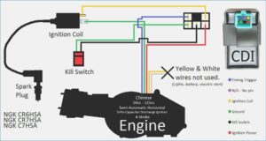
Excellent 250cc Chinese Cdi 6 Pin Wiring Diagram The Best Diagram Wire 150cc