Cable connection balanced and unbalanced soldering schematics how to white noise studio audio cables my second brain xlr connector rca diagram electrical wires taxi meter angle electronics png pngegg custom making diy guide performance hifiman sundara help headphone. Xlr to 1 4 trs connector wired for balanced.
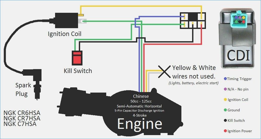
Cdi Wiring Diagram Motorcycle Wiring Kill Switch Electrical Wiring Diagram
An explanation and diagram showing how to wire an xlr cannon connector to a 1 4 inch stereo jack connector.

Balanced Xlr Wiring Diagram. XLR to 14 TRS Connector wired for balanced mono The usual way to connect a 3-pin XLR to a 14 TRS AKA stereo jack plug is to use the following pin allocation. 35 Mm To Xlr Wiring Diagram. Pin 2 on the xlr is hot and carries the positive going signal whilst pin 3 is cold and provides the return.
Xlr Wiring Diagram neutrik xlr wiring diagram xlr cable wiring diagram xlr connector wiring diagram Every electrical structure is made up of various unique parts. The usual way to connect a 3-pin XLR to a 14 TRS AKA stereo jack plug is to use the following pin allocation. Each part should be set and connected with other parts in particular way.
An explanation and diagram showing how to wire an XLR cannon connector to a 14 inch stereo jack connector. The above diagram shows you the pin numbering for both Male and Female XLR connectors from the front and the rear view. If the signal source is equipped with an output transformer.
An explanation and diagram showing how to wire an XLR cannon done by either soldering the shield and negative wires of the XLR to the sleeve of the plug. Van den Hul Audio CableConnector Wiring Diagrams Female Balanced XLR TO Male Unbalanced RCA Fig. This type of connector is heavier than others and circular in size.
An explanation and diagram showing how to wire an XLR cannon connector to a 14 inch This wiring configuration gives you a balanced mono audio cable. Strip off the cov. Xlr pin 1 to 1 4 plug sleeve.
The first is a more abstract schematic representation while the second looks closer to actual wiring to the boards. XLR 2 hot should go to JACK TIP XLR 3 cold should go to JACK RING XLR 1 ground should go to JACK SLEEVE The TN RN and GN. Collection of xlr wiring diagram pdf.
If the signal source is equipped with an output transformer. In the case of an XLR cable the three wires are called X ground L left hot Although it may look like a standard 14 mm or 18 mm phono plug. Pin 2 on the XLR is hot and carries the positive going signal whilst pin 3 is cold and provides the return.
So if the hot wire at any moment is at 5 volts the cold wire would be at 5 volts. Wiring Diagram includes the two examples and step-by-step instructions that will permit you to definitely really construct your venture. If the signal source is equipped with a cross coupled output stage.
Speakon to xlr wiring diagram. Here is the basic wiring diagram for a standard 3 pin xlr connector used in audio for mics playback machines intercom etc. 3 Pin XLR Wiring Standard.
The easiest way is to solder a link between pins 1 and 3 shield and negative of the xlr rather than trying to solder. Audio Cables and Connections. Xlr to 1 4 trs connector wired for balanced mono the usual way to connect a 3 pin xlr to a 1 4 trs aka stereo jack plug is to use the following pin allocation.
The audio signal is carried in anti-phase on the positive and negative wires and this is decoded at the. XLR pin 3 to 14 plug ring. The rear view is the end you solder from Here are the connections on each pin.
Connector Electronics PinOut. Xlr To 1 4 Trs Connector Wired For Balanced Mono The Usual Way To Connect A 3 Pin Xlr To A 1 4 Trs Aka Stereo Jack Plug Is To Use The Following Pin. XLR Connector is an electrical connector used for the audio signal video signal and electrical power transmission.
I had to have a set of rca to xlrs specially made up by mark grant i had to send him a copy of the wiring diagram and he told me that it was not the conventional method for wiring a rca to xlr cable barco g808s lumagen hdp isf oppo970hd toshiba ep35 tag av32rdp 4 atc t16s atc c4ca svs pb12 2plus2 xbox360 7. This is helpful for each the individuals and for specialists that are looking to learn more on how to set up a operating. 3-Pin XLR Audio Pinout.
Balanced xlr wiring diagram. If the signal source is equipped with a cross coupled output stage. XLR to inch stereo jack plug.
The three pin and five pin XLR pinout is a very standard connection used for audio mic level line level 3 pin and lighting control DMX 5-pin applications. Balanced Xlr Wiring Diagram Wiring Diagram Database Trs Wiring Diagram. Trs Wiring Diagram Headphone Stereo Headphones Wire.
A wiring diagram is a simplified standard photographic depiction of an electric circuit. Some manufacturers especially in vintage equipment do not follow this standard and instead reverse the polarity of pin 2 and 3. In a professional audio system you can see most of the applications.
The usual way to connect a 3 pin xlr to a 1 4 trs aka stereo jack plug is to use the following pin allocation. This article shows the XLR Pinout diagrams for both 3-pin and 5-pin connectors. XLR pin 2 to 14 plug tip.
XLR Pinout Wiring Diagram – Male and Female Connector. This wiring configuration gives you a balanced mono audio cable. Balanced xlr wiring diagram.
Xlr To 14 Inch Mono Wiring Diagram. 5 pin 3 pin XLR wiring pinout information. XLR to 14 TRS Connector wired for balanced mono.
How to wire an XLR Connector balanced A balanced system is used in pro audio with an overall screen covering a twisted pair. Pin Em Estudio Here is a picture gallery about neutrik speakon wiring diagrams complete with the description of the image please find the image you need. In either diagram we only terminating a single input and a single output to the left and right channels.
The correct way to wire balanced audio to the V25 is shown below in two different diagrams below. Balanced Audio Cable Wiring Diagram Wiring Diagram Line Wiring Diagram. On Xlr To 14 Balanced Wiring Diagram.
Van den hul audio cable connector wiring diagrams female balanced xlr to male unbalanced rca fig. If the signal source is equipped with a pseudo balanced output stage. Denon D2000 Amboyna Burl cups J padsMarkl moded and APS V3 balancedHD800 ZeusStax SR-009Oppo PM-3 Focal Utopia with Axios AG cableUltrasone Edition 15 SR-X9000on orderSusvara and RAAL SR1a.
The following is the AES industry standard for balanced audio XLR wiring commonly known as pin-2 hot. 3 Pin XLR connectors are standard amongst line level and mic level audio applications. Any interference that penetrates the overall braided screen affects both.
If not the structure wont function as it ought to be. XLR pin 1 to 14 plug sleeve. Youll also discover each XLR pins polarity.
It shows the elements of the circuit as simplified forms and the power and also signal connections between the tools. Wiring diagram speakon xlr. 1 4 inch jack wiring xlr to 1 4 trs connector wired for balanced mono the usual way to connect a 3 pin.
Xlr pinout balanced a balanced system is used in pro audio systems xlr wiring diagram shown below with an overall screen covering a twisted pair. As well as speakon to 1 4 wiring diagram in addition neutrik xlr wiring. If you want to use the Lavry XLR outputs you will need an extranal amplifier with balanced inputs and balanced headphones output.
Xlr connector speakon banana electrical cable. If the signal source is equipped with a cross coupled output stage. MICROPHONE CABLE BALANCED ACCORDING TO IEC-NORM.

Harley Davidson Wiring Diagram Agnitum Me And At Harley Wiring Diagram Pocket Bike Sportster Home Electrical Wiring

Electronic Circuit Projects Electronic Engineering Audio Cables

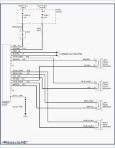
Inspirational Wiring Diagram Pioneer Diagrams Digramssample Diagramimages Check More At Https Nostoc Pioneer Car Stereo Car Stereo Car Audio Installation

Car Alarm Wiring Diagram On Security Download Throughout Diagrams With On Car Alarm Installation Wiring Diagr Car Alarm Viper Car Alarm

Honda Xl100 Motorcycle Complete Wiring Diagram All About Wiring Diagrams Electrical Wiring Diagram Motorcycle Paint Jobs Honda

Marine Power Inverter Wiring Diagram Trailer Wiring Diagram Diagram Wire

Elegant Wiring Diagram Nz Diagrams Digramssample Diagramimages Wiringdiagramsample Wiringdiagram Check M Electric Bike Electric Bike Diy Motorcycle Wiring

55 Awesome Dual Radio Wiring Diagram Marine Radio Car Stereo Radio

Unique Yamaha Moto 4 Wiring Diagram Yamaha Golf Carts Electric Golf Cart Diagram

Installing Turn Signals Motorcycle Wiring Electrical Diagram Electrical Wiring Diagram

110cc Chinese Atv Wiring Diagram Schaferforcongressfo Motorcycle Wiring Pit Bike Trailer Wiring Diagram

On Free Wiring Diagrams Motorcycle Wiring Diagram Electrical Wiring Diagram

Inspirational Wiring Diagram For Rock Lights Diagrams Digramssample Diagramimages Wiringdiagramsample Wiringdia Bar Lighting 12v Led Lights Led Light Bars
Wire Harness Wiring Cdi Assembly For 50 70 90 110cc 125cc Atv Quad Coolster Go Kart Wish In 2022 Motorcycle Wiring 90cc Atv Chinese Scooters

Unique Wiring Diagram Symbols Meanings Diagrams Digramssample Diagramimages Check More At Https Electrical Wiring Diagram Electrical Diagram Circuit Diagram

Running Cat 6 Wire Google Search Wp Themes Cat6 Cable Diagram

568 B Wiring Diagram Ethernet Wiring Cat6 Cable Home Electrical Wiring

Ez Go Golf Cart Wiring Diagram Gas Engine Free Wiring Diagram Electrical Wiring Diagram Electrical Diagram Ezgo Golf Cart

Unique Trane Heat Pump Thermostat Wiring Diagram Thermostat Wiring Electrical Diagram Trane Heat Pump