Maximum RLA 405 Amps. 3 in 1 starters like the supco that you have pictured can and will and blak wires to the compressor the 2 left over leads will connect to the 2.
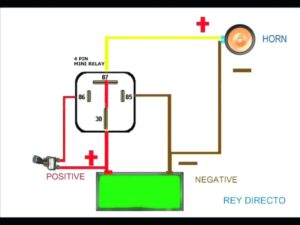
60 New 87a Relay Wiring Diagram Relay Basic Electronic Circuits Electronic Circuit Projects
Simple family refrigerator repair using Supco 3N1 capacitor relay kit.

Supco 3 In 1 Wiring Diagram. Supco 3 In 1 Wiring Diagram. PRO TJ90RCO 3 in 1 Relay Combo Kit Part AP Since SUPCOs introduction of the 2-wire hard start kit in the late s there has been Figure one 1 shows the wiring diagram for the OEM style. Supco 3 N 1 Relay Overload Start Capacitor part number URC0810.
However it doesnt mean connection between the wires. Rated for 112 HP to 15 HP compressors. Replaces all 3 electrical components on all capillary systems.
110 to 125VAC Solid-state Hardstart Relay includes relay overload and start capacitor. Wiring Diagram Installation Instructions Printed on Package. Supco 3 in 1 hard start kitsupco 3 in 1 startsupco 3 in 1 starter kitsupco 3 n 1 start unit rcosupco universal 3 n 1 start put up by admin in Includes wiring diagram and instructions on relay.
So it isnt the 3-n-1 though. Numbers URCO 3 in 1 Relay Overload Capacitor for 112 through 15 HP Compressors. Supco RCO 3 n 1 START Hard Start Kit.
Basically that hard start has 5 wires. Sometimes the wires will cross. My supco has a diagram 2 reds go to run capicitor according to pic this.
Questions Answers Wiring diagram may not be correct for your fridge so you may have to change wires. Supco 3 in 1 wiring diagram Hard Start Relay Wiring Diagram New Best Supco 3 In 1 Wiring Diagram Diagram. Works with 112 – 15 Horsepower Hp Compressors at 115 Volts.
Just wire it across your. This is a Solid State Relay Overload Start Capacitor Combination. This kind of photograph Supco 3 In 1 Wiring Diagram Luxury Rc Supco Refrigerator Relay Overload Start Run Capacitor 1 4 1 above will be classed having.
By September 23 2021. As stated earlier the lines at a supco 3 in 1 wiring diagram signifies wires. Here is a 3n1 with the diagram on it.
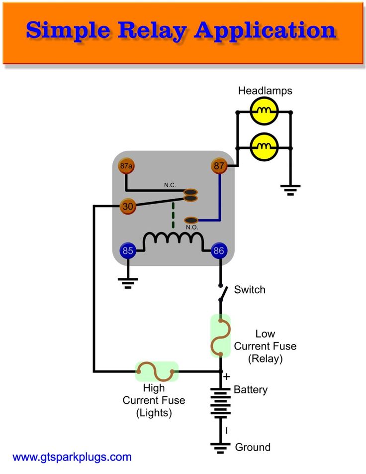
Click on the image to enlarge and then save it to your computer by right clicking on the image. Combining a potential relay and start capacitor the 3 series provides a true 3 wire solution. Get shopping advice from experts friends and the community.
As stated earlier the lines at a Supco 3 In 1 Wiring Diagram signifies wires. The 3 in 1 has 2 more wires that I am. The 3-Series hard starts provide the service professional with an OEM option when the application calls for a hard start.
Step 6 Grasp the 3 n 1 relay box and locate the five wires protruding from it. Microsquirt as i o box 4 wiring pin name color in out function max amp 1 12v in red in main power feed 1a 2 canh blue yellow comms can communications 3 canl blue red comms can communications 4 vr2 vr2 in wheel speed in 2 ve 5. You put red to the right run.
Supco 3 In 1 Wiring Diagram Wiring Diagram Supco 3 In 1 Wiring Diagram. Supco 3 N 1 Wiring Diagram. There are three color-coded wire plugs.
My supco has a diagram 2 reds go to run capicitor according to pic this There should be two wires on the 3 IN 1 that have no connectors on. It includes guidelines and diagrams for various types of wiring methods and other items like lights windows and so forth. Hover over picture to Zoom.
The diagram will display which terminals on the compressor have positive negative and neutral charges. Domestic and Commercial Refrigerators and Freezers. Wiring Diagram Pics Detail.
Wire a Supco 3 n 1 relay box to your refrigerators compressor. Used on refrigeration systems with or without run capacitors. How to install a 3 in 1 install relay start cap overload.
Good for 14 – 13 HP. SUPCO stock number RC0410. Supco 3 In 1 Wiring Diagram Wiring Diagram Supco 3 In 1 Wiring Diagram Wiring Diagram consists of numerous in depth illustrations that present the link of various items.
Hover over picture to Zoom. Fixed avanti compact refrigerator dog ate everything in the back applianceblog repair forums help need on installing 3 1 start kit crosley supco 1955 gm frigidaire new relay wiring problems how to fix your or freezer quickly and cheaply john s tech blog now for systems with run. Furthermore Wiring Diagram provides you with enough time body in which the projects are to become completed.
Examine the wiring diagram on the compressor unit. Therell be primary lines that are represented by L1 L2 L3 and so on. I thought I would change out the relay using a hard start 3 in 1.
I got the compressor wires hooked up but am not sure which of the original 3 that were going into the compressor to connect to the two line out from the supco. 3-wire hard a 3-wire hard start but installation is made simpler and cost is usually lowerHow to hook up an electric motor start or. You do not need the capacitor or the overload or the relayThe kit has all of them thangs built in to it.
Wiring Diagram and Installation Instructions Printed on Package. 3W1–3 WIRE HARD START KIT. Help need on installing 3 in 1 start kit on Crosley refrigerator.
Wiring Diagram and Installation Instructions Printed on Package. I have a kenmore chest freezer 22519702 The freezer wasnt 2 years old and it just stopped working. Combining a potential relay and start capacitor the 3 series provides a TRUE 3 wire solution.
Supco 3 in 1 hard start kit supco 3 in 1 start supco 3 in 1 starter kit supco 3 n 1 start unit rco supco universal 3 n 1 start put up by admin in includes wiring diagram and instructions on relay. That one comes with the capacitor and the one I got doesnt. Collection of supco 3 in 1 wiring diagram.
Youll be capable to understand precisely if the assignments should be finished which makes it much easier for you to correctly control your time and effort. Supco 3 in 1 wiring diagram hard start relay wiring diagram new best supco 3 in 1 wiring diagram diagram. I have the 3 wires from the 3 in 1 start connected to the 3 prongs coming out of the compressor.
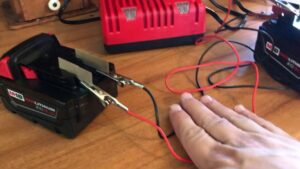
3 wire hard a 3 wire hard start but installation is made simpler and cost is usually lower how to hook up an electric motor start or run capacitor. Supco 3 in 1 wiring diagram. Before touching any of the wiring connected to startup or motor run capacitors you should discharge them.
Use with or without Run Capacitor. Injunction of two wires is generally indicated by black dot on the junction of 2 lines.

45 Beautiful 5 Pin Relay Wiring Diagram Car Horn Electrical Wiring Diagram Automotive Electrical

Pin On Diy Electrical

45 Beautiful Danfoss Compressor Relay Wiring Diagram Compressor Electrical Circuit Diagram Air Conditioner Maintenance

Push Button Ignition Switch Wiring Diagram New Boat Wiring Kill Switch Electrical Wiring Diagram

Unique Single Phase Capacitor Start Capacitor Run Motor Wiring Diagram Electrical Wiring Diagram Electrical Circuit Diagram Capacitor

Frigidaire Wiring Diagram Newer Sc 1 St Appliance Aid Best In Frigidaire Wire Diagram

Best Bosch Relay Wiring Diagram 5 Pole Electrical Outlet Symbol 2018 Electrical Circuit Diagram Light Switch Wiring Electrical Wiring Diagram

Intertherm Thermostat Wiring Diagram Wiring Forums Diagram Diagram Chart Electrical Wiring Diagram

Cat Starter Relay Wiring Diagram Auto Wiring Diagrams Engine Control Unit Automotive Electrical Electrical Wiring Diagram

Unique Wiring Diagram For Chinese 110cc Atv Wiring Diagram Chinese Atv Wiring Diagrams Roketa 11 Motorcycle Wiring Electrical Diagram Electrical Wiring Diagram

Starter Wiring Help Electrical Circuit Diagram Electricity Wire

Lewmar Windlass Wiring Diagram Upgrade Windlass Power Wiring Of Lewmar Windlass Wiring Diagram With Windlass Wiring Diagram For Windlas Diagram Power Wire Wire

New Wiring Diagram Ice Maker Diagrams Digramssample Diagramimages Wiringdiagramsample Wiringdiagram Check Electric Stove Electrical Diagram Electric Oven

30 Unique Refrigerator Start Relay Wiring Diagram A Control Relay I Electrical Circuit Diagram Air Conditioner Maintenance Refrigeration And Air Conditioning

Capacitors For Compressor Wiring Diagram Ac Capacitor Capacitor Compressor

Copeland Potential Relay Wiring Diagram Run Capicator For Electrical Circuit Diagram Hvac Air Conditioning Diagram

Awesome Three Wire Alternator Wiring Diagram Gm Diagrams Digramssample Diagramimages Wiringdiagramsample W Alternator Electrical Diagram Voltage Regulator
55 New Potential Relay Wiring Diagram Electrical Circuit Diagram Ac Capacitor Electrical Diagram

Diagram 240v Airpressor Wiring Diagram Full Version Hd Electrical Circuit Diagram Air Conditioner Maintenance Electronic Parts