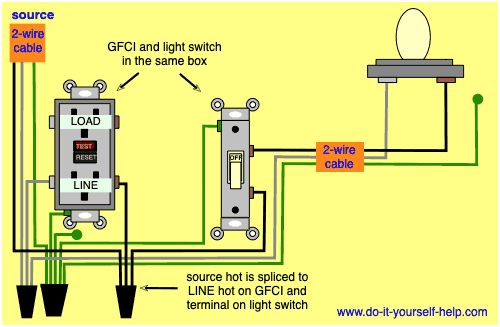
See Diagram A. Place the switch in the hot wire going to the line side of the GFCI outlet.
Wiring Diagram For A Gfci Outlet And Light Switch In The Same Box Outlet Wiring Electrical Wiring Light Switch Wiring
To properly wire GFCI or ground fault circuit interrupter receptacles turn off the power to the circuit youre working on and unscrew the cover plate on the outlet box.

Wire Gfci To Switch. It takes practice so get the wires in there so it doesnt look like a knot. Connect ground wires as usual switch and outlet. Ive been able to do everything except shut off the new light.
Run the neutral wire uninterrupted to the line side of the GFCI outlet. Do the installation improperly and it can potentially deadly. The 2 wires in the lower right are for the new light.
The 4 wires on the right connect to operate fan and switch. On the new GFCISwitch combo there is a load and line side and two black wires coming out of the back that are meant to control the switch. If there is only 1 cable containing 2-3 wires connect the white line wire to the silver or white terminal and connect the black wire to the brass terminal which is the.
Disconnect wires from the existing outlet. Run the neutral wire uninterrupted to the line side of the GFCI outlet. Next the wiring may extend out to the light switch where only the black power wire is connected through the switch and the white neutral wires are spliced together.
Gfci wiring diagram with switch. Electrical gfci outlet wiring diagram diagrams do it for multiple receptacle and connection a light switch off with outlets how to install dengarden circuit from wire breaker 20a gfi ground fault interrupter adding after gcfi ge 15 amp self test white protection installation tips testing leviton can t reset anko. In this configuration the outlet only works when the switch is on.
On the load side there is one wire leading up to the lighting fixture. To wire this circuit the source wires are connected to the LINE terminals on the receptacle half of the combo. Note that the ground for both the income and outgoing is.
If you want to protect the light wire power to the GFCI LINE terminals and connect the switch using the LOAD terminals. If there is only 1 cable containing 2-3 wires connect the white line wire to the silver or white terminal and connect the black wire to the brass terminal which is the. If for some reason you wantneed the light circuit to be GFCI protected you simply run the wire from the load side of a GFCI outlet and wire it like any other light switch and lighting device.
Your help is very much appreciated. As discussed before GFCI also known as ground fault circuit interrupter is a protection device against electric shock which detects the ground faults and leakage currents especially in outdoor and watery areas such as bathroom kitchen laundry etc. Duplex receptacles have 4 screws for termination points along with a green screw dedicated for ground.
Plug a clock radio or light into the outlet. However it would be best to provide the power for an exterior GFCI outlet from a separate circuit instead of tying into the bathroom circuit. The white wires tie together to complete the return side of the circuit while the black wire hot wire runs through the 2-way switch and out to the outlet.
It means all the connected loads to the load terminals of GFCI are protected. Ground Fault Circuit Interrupter. Wiring for a switch and gfci receptacle in the same box is also shown.
Who is sissy in the 5th wave. Hi Rick from what you have described the wiring to the 2nd 3way switch could be converted to provide power to a GFCI outlet if the power feed is in fact at the first switch box. Place the switch in the hot wire going to the line side of the GFCI outlet.
Remove mounting screws and gently pull the switch out of the wall box. The built-in switch controls an unprotected light fixture on a separate electrical source. On the left side with 12-3 wire the black and white power the gfci green to ground and the red wire does nothing.
In this GFCI outlet wiring and installation diagram the combo switch outlet SPST single way switch and ordinary outlet is connected to the load side of GFCI. Cut with wire trimmers if necessary. Can I Wire My Gfci Outlets In Series With Another Docking Drawer.
Turn the power back on at the circuit-breaker panel. This diagram illustrates wiring a GFCI receptacle and light switch in the same outlet box a common arrangement in a bathroom with limited space. The other switch wire is connected to the LOAD hot terminal on the combo device.
If replacing an existing GFCI label the black and white wires on the Line and Load terminals. Is the proper way to wire this. Run the neutral wire uninterrupted to the line side of the GFCI outlet.
GFCI Combo Switch and Outlet Wiring Circuit Diagrams and Installation. To wire a gfci circuit breaker see this link and wire a gfci switch combo at this link. Place the switch in the hot wire going to the line side of the GFCI outlet.
To wire a gfci circuit breaker see this link and wire a gfci switch combo at this link. Replace the receptacle screw it back into the box and attach the cover plate. To control the GFCI Power the GFCI through the switch attaching those switched power leads to the GFCI LINE terminals.
This diagram illustrates the wiring for a circuit with 2 gfci receptacles followed by a light and switch. Connect the bare ground wire to the green Ground screw. In this application the GFCI outlet has the power entering the LINE side and extends through the GFCI outlet and is fed out to the circuit from the LOAD side of the GFCI outlet.
It will be used to switch a dust collection unit on and off in my workshop. 12-9-17 Its over 9000. A 2-wire cable runs from there to the garbage disposal and the black wire is spliced with one of the built-in switch wires.
Wiring a GFCI Outlet and a Light Switch. Wiring a GFCI Outlet with a Light Switch and Protected ReceptacleThe built-in switch controls an unprotected light fixture on a separate electrical source. Wiring A Gfci Outlet With A Light Switch Diagram Database.
Prepare wires by making sure they are straight and not touching each other. Test the GFCI by pressing the Black Test button on the outlet. The toggle switch in the combo switch outlet controls the first light bulb while the single way.
The source to the outlet is connected to the LINE terminals on the gfciThe LOAD terminals are connected to the standard receptacle using a 2-wire cable.

How To Install And Troubleshoot Gfci Home Electrical Wiring Wire Switch Outlet Wiring

Gfci Wiring Diagram With The Switch Separate Gfci Outlet Wiring Home Electrical Wiring

How To Wire Gfci Combo Switch Http Waterheatertimer Org How To Wire Gfci Html Gfci Combo Wire Switch Gfci Light Switch Wiring

Image Result For Wiring Outlets And Lights On Same Circuit Electrical Wiring Home Electrical Wiring Gfci Wiring Diagram

Gfic Protected Switch Outlet Wiring Gfci Home Electrical Wiring

How To Wire Switches Wire Switch Home Electrical Wiring Basic Electrical Wiring

Adding A Switch To An Existing Gfci Google Search Gfci Light Switch Home Electrical Wiring

Electrical Gfci Outlet Wiring Diagram Outlet Wiring Gfci Electrical Wiring

Multiple Gfci Outlet Wiring Diagram Outlet Wiring Electrical Wiring Gfci
Wiring Diagram For A Switched Gfci Outlet Outlet Wiring Wiring Outlets Home Electrical Wiring

Gfci Wiring Diagram With A Light And Switch Not Protected From Ground Faults Outlet Wiring Electrical Wiring Outlets Diy Electrical

Wiring Diagrams For Ground Fault Circuit Interrupter Receptacles Www Do It Yourself Help Com Outlet Wiring Electrical Wiring Outlets Diy Electrical

Gfci Receptacle And Switch Same Box Electrical Wiring Home Electrical Wiring Outlet Wiring

Gfci Outlet Wiring Diagram Basic Electrical Wiring Home Electrical Wiring Electrical Wiring Diagram

My Wife And I Just Bought Our First House And Needed To Replace Many Of The Receptacles As They Are Loose And Most Are Gfci Light Switch Wiring Outlet Wiring

How To Wire Gfci Combo Switch Outlet Gfci Switch Outlet Wiring Electronic Engineering Outlet Wiring Gfci

Wiring Diagram For A Gfci Outlet And Light Switch In The Same Box Outlet Wiring Electrical Wiring Light Switch Wiring

Gfci Outlet Wiring Diagram Electrical Wiring Diagram Outlet Wiring Home Electrical Wiring

Wiring Switches And Outlets Gfci Outlet Wiring Wire Switch