There are four basic wiring combinations. Security starter relay controlled car starter wiring diagram.
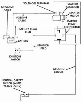
Image Result For Dodge Starter Relay Wiring Diagram Car Alternator Automotive Electrical Electrical Wiring Diagram
It uses three.

Basic starter motor wiring diagram. In the tractor starter wiring diagram the circuit starts with the battery at the left of the. One for the positive battery cable and the other for the thick wire that powers the starter motor itself see the diagram below. A motor starter is a combination of devices used to start run and stop an ac induction motor based on commands from an operator or a controller.
A typical starter solenoid has one small connector for the starter control wire the white connector in the photo and two large terminals. The security starter relay controlled car starter wiring diagram is as shown in the. They show the relative location of the components.
They can be used as a guide when wiring the controller. To ensure that the starter can stall automatically and the starter circuit not connected after the engine starts some cars adopt the compound relay circuit with safety driving protection. This is a picture of the basic principles of any starting system.
The following diagram is shown for 3 phase motor control of a delta star connection. A full voltage non reversing 3 phase motors. The common components in a wiring diagram are ground power supply cord and connection outcome gadgets switches resistors reasoning gateway lights etc.
It utilizes a main tained contact type of pilot device such as a thermostat float switch or presence sensor. If you have a 120v coil instead of running a line from coil overload l2 you must run coil overload neutral. Figure 1 typical wiring diagram.
Basic wiring for motor contol circuitry of a starter two wire control two wire control circuits or low voltage release one of the common control wiring circuits used is known as two wire or low voltage release lvr. Basic wiring for motor control technical data. The basis principles are the battery.
To check out a wiring diagram first you need to recognize what basic components are included in a wiring diagram as well as which pictorial icons are used to represent them. Once the principles of the starting system can be understood then any variations of the wiring can be easily understood. 3ph starter 3ph motor line voltage control three phase 3ph motor starter controlling a three phase motor rev 08 aug 2006 the above wiring diagram assumes your magnetic starter has a 240v coil.
Figure 1 is a typical wiring diagram for a three phase magnetic motor starter.

Gm Starter Solenoid Wiring Diagram Post Date 07 Dec 2018 78 Source Http Moesappaloosas Com Wp Automotive Mechanic Truck Repair Automotive Repair

Starter Diagram Automotive Repair Motorcycle Wiring Automotive Mechanic

Universal Ignition Switch Wiring Diagram Boat Wiring Kill Switch Electrical Wiring Diagram

10 Small Engine Starter Switch Wiring Diagram Engine Diagram Wiringg Net In 2020 Boat Wiring Kill Switch Trailer Wiring Diagram

Volvo Penta Starter Wiring Diagram Digital Motor Wki Pinterest And Volvo Volvo Trucks Engineering

Wiring Diagram Symbols Automotive Http Bookingritzcarlton Info Wiring Diagram Symbols Auto Automotive Electrical Electrical Wiring Diagram Electrical Wiring

Starter Solenoid Wiring Diagram Deltagenerali Me Within Ford F150 Remote Car Starter Car Starter

Image Result For Car Starter Relay Wiring Diagram Trailer Light Wiring Automotive Mechanic Electrical Circuit Diagram

Starter Solenoid Wiring Diagram Starter Motor Ford Tractors Starter

New Wiring Diagram Car Charging System Diagram Diagramtemplate Diagramsample Alternator Electrical Diagram Electrical Circuit Diagram

Small Engine Starter Motors Electrical Systems Diagrams And Killswitches Small Engine Starter Motor Automotive Repair

Starter Solenoid Wiring Diagram Ignition Motorcycle Wiring Electrical Wiring Diagram Alternator Working

Smart Car Starter Motor Wiring Diagram Model T Ford Forum In Boat Wiring Mercury Outboard Electrical Wiring Diagram

Three Phase Dol Starter Wiring Diagram Component Single Motor Circuit Contactor Starte Full Size Cont Comandos Eletricos Eletricidade Basica Projetos Eletricos

Pin By Dean Hardiman On Auto Wiring Simple To Use Diagrams Car Starter Engine Block Motorhome

Wiring Diagram For Garden Tractors With A Delco Remy Starter Generator Electrical Diagram Electrical Wiring Diagram Delco

Http Brianesser Com Wp Content Uploads 2012 09 Alternatorwiringoverview 1973to1985buick Jpg Alternator Car Alternator Chevy 350 Engine

Starting System Diagram Starter Motor Motorcycle Wiring Automotive Repair

Direct On Line Dol Motor Starter Basic Electrical Wiring Electrical Circuit Diagram Circuit Diagram