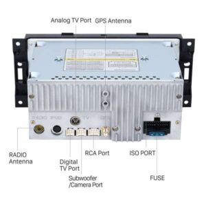
It shows the components of the circuit as simplified forms and also the power and also signal links in between the tools. One way paging system block diagram figure 1 features 1 3 6 and 24 expandable with v 2925a in 24 zone increments for up to 96 zone page control units available.

Diagram Bogen Speaker Wire Diagram Full Version Hd Quality Wire Diagram Family Tree Diagram Emericgatelier Fr
Bogen paging system wiring diagram appealing system speaker intercom paging clock bell systems we design install bogen wiring diagram 100 amplifiers part 4 1959 82 bogen ddu250 mic wiring diagram wiring diagram bogen wiring diagram wiring diagram bogen tpu250 users manual 54 5900 01r1 bogen communications dft 120 digital paging feedback.

Bogen paging system wiring diagram. A wiring diagram is a simplified conventional pictorial representation of an electric circuit. One way all call to all speakers available. Variety of bogen paging system wiring diagram.
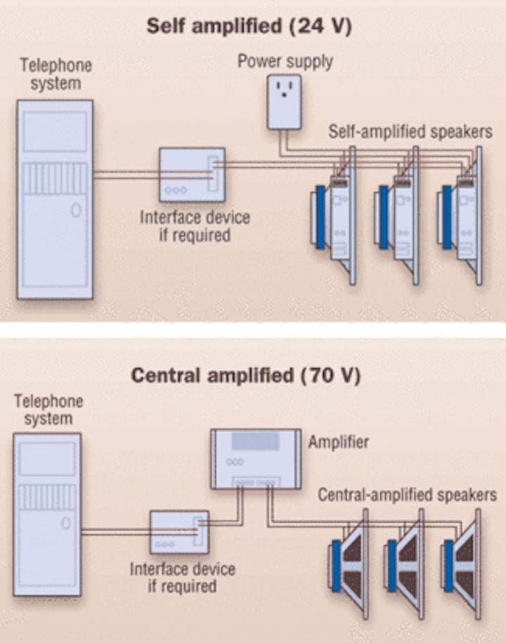
The 70 volt system delivers 100 of its full rated power and the 24 volt system encounters power loss due to dc line loss. The 70 volt system operates on a one pair cable. Collection of bogen paging system wiring diagram.
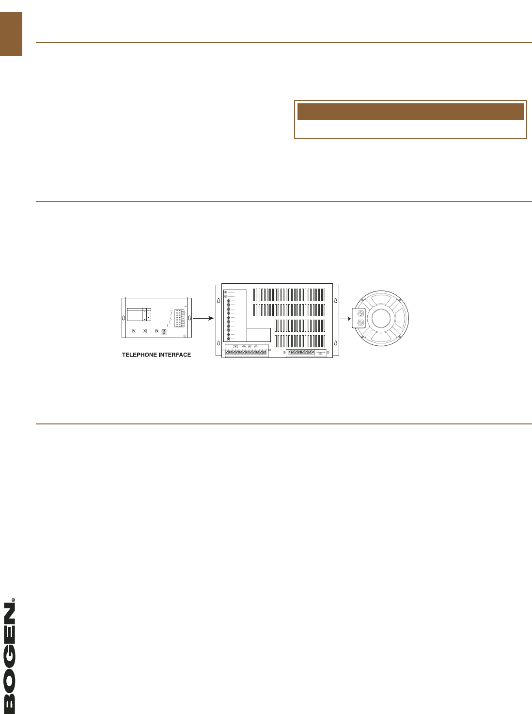
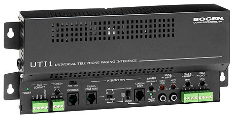
The 24 volt system on a two pair cable. Some paging equipment such as bogen s pcm2000 uti1 and uti312 paging interfaces include a test tone that is sent to all speakers in the system so installers can check the. Connect the bogen amplifier to the ac power outlet 120v ac 60hz.
Set the volume on your bogen amplifier to a 1 2 turn. Bogen communications uti 1 allows for one zone paging that is you can only page all the connected loudspeakers at once speakers need to be chain linked. Sound adjust ments or additional speakers may be needed.
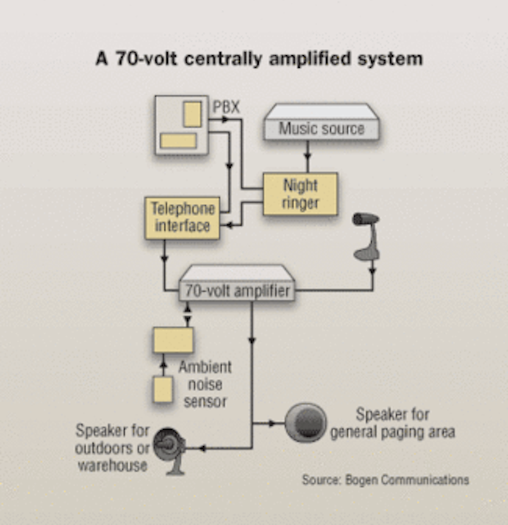
Volume controls and amplifiers in each speaker. It does have a connection to speakers that will relay only the paging from the telephone and another one that will mix in music from the music source giving you a choice between the two. System covers an area is to test it.
It shows the parts of the circuit as streamlined forms and also the power and signal connections in between the devices. Series parallel speaker wiring wire loss chart notwithstanding bogen s efforts to ensure the accuracy of these drawings bogen makes no representation or warranty express or implied as to the accuracy or reliability of the drawings or any statement depiction or implication set forth therein or arising therefrom as to the product to which. Paging system the most important thing to remember about surveying designing and quoting a telephone paging system is that there is no mystery or magic involved.
A wiring diagram is a streamlined conventional photographic depiction of an electrical circuit. Access the paging from the telephone system and listen on the handset for the confirmation tone double beep. Never install a paging system and leave the site without testing it.
If you re working in medium to large projects the 70 volt system is economical and the 24 volt system is not. The successful system design is one that combines good old fashioned common sense with a few rules of thumb and commonly practiced installation guidelines.

Bogen 15 Watt Amplifier By Bogen 214 89 Bogen 15 Watt Amplifier Bogen 15 Watt Telephone Paging Amplifier Tel Input Amplifier Electronics Audio Electronics

Diagram Bogen Paging System Wiring Diagram Full Version Hd Quality Wiring Diagram Nhlsuspensions Zatro It

Bogen Tpu100b Telephone Paging Amplifier Bogen Paging
Paging System Design A Step By Step Process Cabling Installation Maintenance
System Design Guide Bogen Catalog 104
Hyundai Msu 113c Heem 2msu 113c Heem 2 Motor Auto Control Unit Control Unit Hyundai The Unit

Bogen 15 Watt Amplifier By Bogen 214 89 Bogen 15 Watt Amplifier Bogen 15 Watt Telephone Paging Amplifier Tel Input Amplifier Electronics Audio Electronics

Bogen Uti312 Multi Zone Page Controller By Bogen 218 98 Bogen Multi Zone Paging Controller 3 To 12 Zone Provides Mul Speaker System Control Installation

Pin Von Dieter Muller Auf Rohrenverstarker

Pin Di Weider Su Elettronica Informatica Schema Elettrico Elettronica Informatica

Dave Schmarder S 1625 All Wave Receiver Schematic Radio Hf Radio Radio Design
Telephone Paging Interface Uti1 Bogen Paging
Choosing The Right Paging And Alert System Cabling Installation Maintenance
Https Encrypted Tbn0 Gstatic Com Images Q Tbn 3aand9gcraxe Lcxfkeyppefca4eg01m Dx4mr5mzmduwasvflz1en1ik9 Usqp Cau

Wifi Wan Router 3m Wi Fi Antenna Extension Cable Rp Sma By Oem 1 67 Package Includes 1 X 3m Wifi Antenna Rp Sma Extension Cable For Rp Sma Router Antenne

Diagram Hospital Paging System Wiring Diagram Full Version Hd Quality Wiring Diagram Wiringautopdf Plurifit Fr