A solenoid valve is a combination of two basic functional units. Valve less base voltage jb 240 60 220 50 ja 120 60 110 50 jc 24 60 24 50 fb 24vdc 1 8 w da 24vdc 5 4 w df 24vdc 12 7 w manual operator 1 non locking 2 locking electrical connection dm plug in dg plug in w ground note.

Electrical Light Wiring Diagram With Light Switch Wiringdiagram Org Electric Lighter Electricity Electric Motor
Is it that the solenoid valve on the pneumatic stop valve can be two wired three wired or four wired.

Ac solenoid valve wiring diagram. Although the wiring of solenoid valve is simple but poeple still encouter problems when wiring the solenoid valve to other devices. Solenoid operator dm dxx p x xx single pressure models 5 2. White ground wire not part of harness supplied.
Both the solenoid and electronic controls. Variety of 12 volt solenoid wiring diagram. Assortment of solenoid valve wiring diagram.
You will need one individual wire for each solenoid valve and one common wire to be shared by all the solenoid valves. We also have repair guides for your vehicle simply follow the link below and enter your vehicle s year make model and engine to find the info you need to do the job right. A solenoid electromagnet with its core a valve body containing one or more orifices flow through an orifice is shut off or allowed by the movement of the core when the solenoid is energized or de energized.
Here are some problems for your reference. Be sure compressor body is grounded. Ground wire required for solenoids 30 volts and above.
To begin wiring at the controller with the power off pull back the outer sheathing exposing the individual wires. The savings in power usage over the installed life of the valve will lower the total cost of ownership. Connect according to trinary switch wiring diagram.
5 core irrigation cable. Install solenoid pointing down. Asco valves have a solenoid mounted directly on the valve body.
A system pump down utilizes a solenoid valve in the liquid line when the system set point temperature has been satisfied the solenoid valve will close. You may have noticed a trend you will always require at least one extra wire. A conventional solenoid with the same performance can draw as high as 17 watts of power.
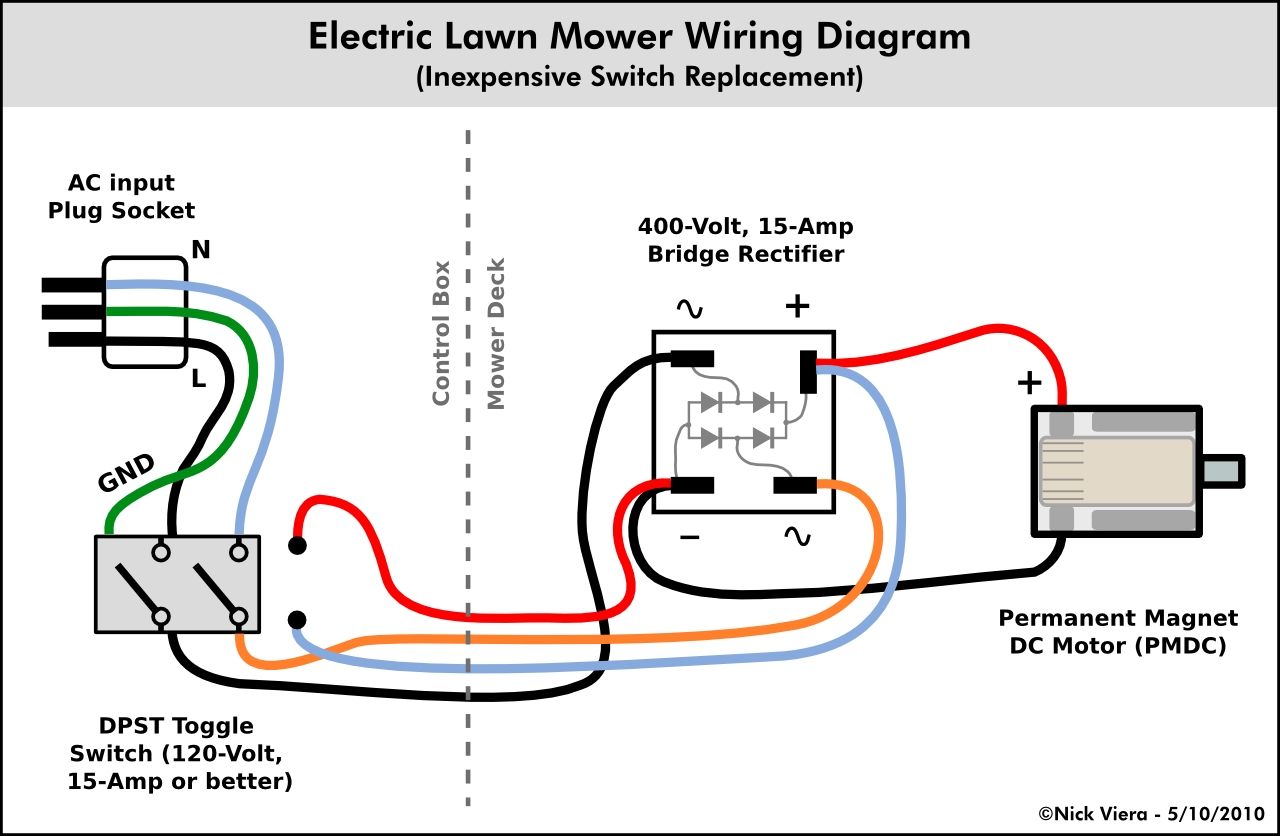
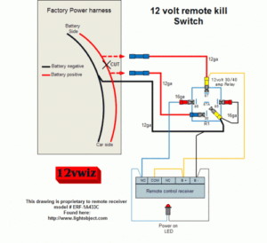
It shows the parts of the circuit as streamlined forms and the power and signal links in between the gadgets. The compressor will continue to pump refrigerant into the condenser and or receiver drawing it from the low side of the system. A wiring diagram is a streamlined conventional photographic representation of an electric circuit.
Normal to get very hot during operation. It reveals the parts of the circuit as streamlined forms and the power as well as signal links between the devices. The new solenoid draws only 1 2 watts of power for 12 24v dc and 1 5 watts for 24 120v ac dc 100 240v ac dc.
Connect as shown typical compressor wiring. Blue wire is a c compressor. A wiring diagram is a streamlined standard pictorial representation of an electrical circuit.
Green wire is heater control valve. The solenoid valve on the pneumatic valve is generally three wired. Browse the excerpts below to find out how to access automotive repair guides through autozone rewards.

Best 12v Relay Wiring Diagram Pin At Switch 5 How To Wire A Electrical Diagram Circuit Diagram Automotive Electrical

Visit The Post For More In 2020 Electrical Circuit Diagram Circuit Diagram Electric Circuit

Small Engine Solenoid Wiring Diagram In 2020 Ignition Coil Electrical Diagram Kohler Engines

Split Ac Wiring Diagram Pdf Package Air Conditioner Definition Throughout Refrigeration And Air Conditioning Air Conditioner Air Conditioning System Design

27 Ford Alternator Wiring Diagram Internal Regulator Bookingritzcarlton Info Voltage Regulator Diagram Alternator

Unique Wiring Diagram Ac Split Mitsubishi Diagram Diagramtemplate Diagramsample Heat Pump Refrigeration And Air Conditioning Thermostat Wiring

Razor Electric Scooter Wiring Diagram Also Contactor Relay Wiring Diagram Furthermore Simple Electrical Circuit Diagram Razor Electric Scooter Circuit Diagram

Razor Electric Scooter Wiring Diagram Also Contactor Relay Wiring Diagram Furthermore Simple Electrical Electrical Circuit Diagram Circuit Diagram Electricity

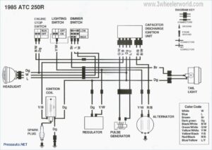
Gy6 Cdi Wiring Diagram Wiring Diagrams Electrical Wiring Diagram Kill Switch Motorcycle Wiring

Pin By Student On Cooling Electrical Wiring Diagram Electrical Wiring Refrigeration And Air Conditioning

Daikin Ac Wiring Diagram Air Conditioning System Building Hvac Heat Pump System

12 Car Aircon Wiring Diagram Car Air Conditioning Ac Wiring Ac Compressor

Motor Control Center Wiring Diagram With Images Electrical Diagram Motor Circuit Diagram

Simple Dc Solenoid Valve Circuit How To Size Components Circuit Circuit Diagram Components

Wiring Diagram Car Air Conditioning Diagram Diagramtemplate Diagramsample Air Compressor Pressure Switch Diagram Air Compressor

Run Capacitor Wiring Diagram Blurts Me Inside Starting

4 Wire Alternator Wiring Diagram On Luxury One 83 With Showy In 1 Pdf Download

Electrical Wiring Diagrams For Air Conditioning Systems Part Two Electrical Knowhow Electrical Wiring Diagram Air Conditioning System Ac Wiring


