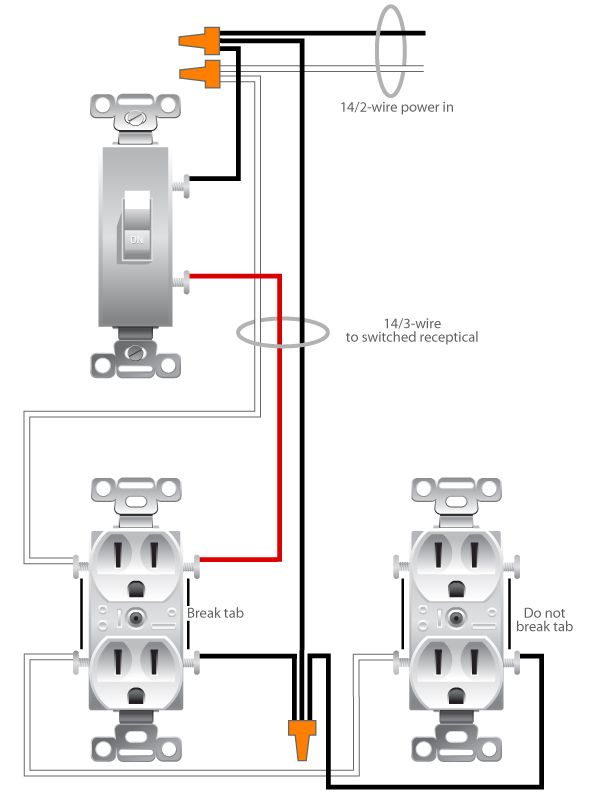
The diagram below shows the power entering the circuit at the grounded outlet box location then sending power up to the switch and a switched leg back down to the outlet. The following wiring diagrams show that multiple outlets are wired to a single pole spst switch one way or two way in us switch.
Wiring A Switched Outlet Wiring Diagram Electrical Online Home Electrical Wiring Diy Electrical Outlet Wiring
Wiring diagram for multiple switched outlets.

Multiple switched outlet wiring diagram. As shown in the fig the switch is firstly installed in the wiring the hot wire from switch feeds all the other parallel connected outlets hence the outlet on off operation can. The source for the circuit is at the switch and 2 wire cable runs to each receptacle outlet. Here 3 wire cable is run from a double pole circuit breaker providing an independent 120 volts to two sets of multiple outlets.
This circuit is wired the same way as the 3 way lights at this link. This diagram shows the wiring for multiple switched outlets on one switch. To wire multiple outlets follow the circuit diagrams posted in this article.
3 way switched outlet wiring. As the diagram at electrical 101 shows the line cable is all you need to supply power to a pair of switches in a single electrical box. After making sure the power is off you strip the black wire in the two conductor cable which also has a ground wire and make a pigtail with two 6 inch lengths of black wire salvaged from a spare piece of cable of the same wire gauge.
At the outlets each is wired using a pigtail splice to make the hot and neutral connections. The neutral wire from the circuit is shared by both sets. Wiring of multiple switched outlets.
For wiring in series the terminal screws are the means for passing voltage from one receptacle to another. Three wire cable runs between the switches and the outlet. Half switched outlet wiring diagram depicting the electrical power feeding into an electrical receptacle box and then going to a switch and to another receptacle.
These electrical wiring diagrams show typical connections. Multiple outlet in serie wiring diagram. Outlets are split wired so that the top half of the receptacle is live all of the time and the bottom of the receptacle is controlled by the wall switch.
This wiring is commonly used in a 20 amp kitchen circuit where two appliance feeds are needed such as for a refrigerator and a microwave in the same location. Outlet wiring for a table lamp or a floor light fixture. Wiring diagram for dual outlets.
In this diagram two 3 way switches control a wall receptacle outlet that may be used to control a lamp from two entrances to a room.

Wiring Diagrams For Multiple Receptacle Outlets Home Electrical Wiring Diy Electrical Outlet Wiring

How To Wire Multiple Outlet In Parallel Electrical Wiring Diagram Home Electrical Wiring Electrical Wiring Electrical Outlets

Wiring Diagram For 3 Way Switch With Multiple Lights Http Bookingritzcarlton Info Wiring Diag 3 Way Switch Wiring Light Switch Wiring Home Electrical Wiring
Multiple Outlets Controlled By A Single Switch Home Electrical Wiring Installing Electrical Outlet Electrical Wiring

Wiring Diagram For 3 Way Switch With Multiple Lights Http Bookingritzcarlton Info Wiring Diagram For Light Switch Wiring Electrical Wiring Diagram Switches

Wiring Diagrams For Ground Fault Circuit Interrupter Receptacles Gfci Home Electrical Wiring Electrical Wiring

2 Way Switch With Electrical Outlet Wiring Diagram How To Wire Outlet With Light Switch Light Switch Wiring Outlet Wiring Electrical Outlets

Wiring Diagrams To Add A New Light Fixture Light Switch Wiring 3 Way Switch Wiring Wire Switch

3 Way Switch Wiring Diagrams 3 Way Switch Wiring Electrical Wiring Electrical Wiring Diagram

3 Way Switch Wiring Diagrams 3 Way Switch Wiring Outlet Wiring Wire Switch

Light Switch Controls Outlet In Same Box Light Switch Wiring Double Light Switch Light Switch

Gfci Outlet Wiring Diagram Outlet Wiring Electrical Wiring Home Electrical Wiring

Wiring Diagram For House Outlets Http Bookingritzcarlton Info Wiring Diagram For House Ou Light Switch Wiring Basic Electrical Wiring Home Electrical Wiring


Wiring Diagrams For Switch To Control A Wall Receptacle Electrical Switches Wiring A Plug Home Electrical Wiring

Wiring Diagrams For Household Light Switches Light Switch Wiring 3 Way Switch Wiring Wire Switch

Wiring Diagram For One Switch Controlling Multiple Lights In Row Light Switch Wiring Home Electrical Wiring Electrical Wiring

Multiple Gfci Outlet Wiring Diagram Outlet Wiring Electrical Wiring Gfci

Wiring Diagram For Two Switches To Control One Receptacle Light Switch Wiring Wire Switch Electrical Wiring