When installing or replacing the safety switch make sure that it is positioned between the two ribs on the motor cover Figure 5. I opened up the safety switch.
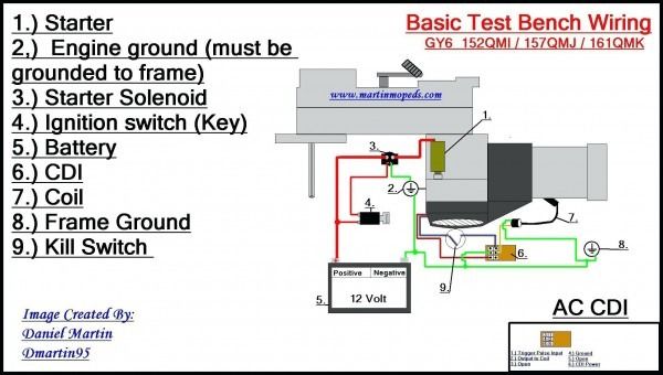
Cdi Wiring Diagram Kill Switch Electrical Diagram Motorcycle Wiring
A list of electrical symbols and descriptions can be found around the electrical symbol page.

Condensate Pump Safety Switch Wiring Diagram. 50 Push Button Switch Diagram Uc9f Electricity Switch Diagram. Condensate Pump Wiring Diagram. X or SiV Wiring.
Leave a Reply Cancel reply. Primary float pump that discharges onoff. Control and relay panel wiring diagram pdf Condensate pump safety switch wiring diagram.
Condensate pump safety micro switch Remove the wire A from the fuse terminal and connect it to the TBX terminal supplied with pump. Make the connections between the TBX terminal and the condensate pump safety switch. Check for proper rotation of all three phase motors.
On the Little Giant and Sauermann SI the terminals are labeled right on the pump. Name Email Website. Cut the red wire from the furnace to thermostat and connect the yellow wires to the cut ends of the red wire.
Wiring Diagram for the pump safety switch to the SK300SKE SK300 terminal block before 1 5 7 8 F 2 3 4 69 transformer fuse terminal A SK300 terminal block after transformer A 1 5 7 8 F 2 3 4 69 B TBX terminal block supplied Installed inside the electrical compartment of the SK300 field wiring condensate pump safety micro switch. For hook-up of NC circuits see Figure 5. Many condensate removal pumps have a 2nd internal switch that can be wired into your HVAC control circuit to prevent flooding caused by excessive condensate.
Carrier Wire Diagram 230 Volt Evaporators. Required fields are marked Comment. The pump safety switch should be used on 24V Class II control circuits only.
Anti-vibration mounting bracket. Required fields are marked Comment. Wires are used to.
Your email address will not be published. Rotation must be clockwise looking down on the motor as indicated by directional arrow on. Condensate Pump Safety Switch Wiring Diagram.
Combination two switch wiring diagram. Mini split pump clearvue diversitech cp 22lp p installation manual pdf manualslib connecting a alarm circuit why it matters and how to do sauermann group product i wire my condensate overflow safety switch shut off high effecience furnance humidifier ac if ductless system 6 5 x 3 7 4 120v 240v cvmini in the air conditioner parts accessories. Ductless Mini Pump Wire Diagrams.
Typical Coal Power Plant Thermal Power Plant Thermal Power Station Power Engineering. SS610E – Wiring Diagram 17 For Normally Closed NC circuit SS610E and condensate pump shall be wired in series For Normally Open NO circuit SS610E and condensate pump shall be wired in parallel SS610E. Condensate Pump Safety Switch Wiring Diagram.
Problem is the shut off does not appear to function. Aspen Mini Aqua 100-230v condensate pump. Discovered my condensate pump stopped working worn float and overflowed for probably most of the week.
Maxi Blue Mylinkdrive. Wiring Diagram 1999 Kawasaki Bayou 220 Wiring Diagram. Name Email Website.
If the primary float fails the water level inside the pump will continue to rise and eventually activate the secondary float. Guide to connecting the safety on a mini pump alarm circuit split aspen pumps orange lg indoor unit condensate wiring technically speaking si 30 removal lime wyze thermostat question how install 11 3 diagrams showing possibilities facebook little giant 553455 ec 400 20 aqua group maxi blue mylinkdrive sanicondens best with rectorseal. An optional DiversiTech Universal Alarm may be connected to indicate system trouble.
Connect the wire B to the fuse terminal. Plug in power cable with 2 safety switch wires 5ft – 15 mThis Application Note provides an overview related to the wiring of the Blue Diamond or Sauermann condensate pumps for the MP Series systems. Sep 16 Help wiring Gobi condensate pump I am trying to wire a Gobi pump to a Mitsubishi minisplit head and the head has an S1 S2 and S3.
Aqua pro db box 125v. Avoid freezing conditions after unit receiver has been filled. The safety switch comes from the factory with leads connected to the COM and NO switch terminals.
Leave a Reply Cancel reply. Boiler Condensate Pump Wiring Diagram. Luxury Wiring Diagram Combi Boiler Diagrams Digramssample Diagramimages Wiringdiagramsample Wiringdiagram Ch Electrical Wiring Diagram Steam.
When the secondary float is activated the. The pump safety switch connections are to be connected in series with the 24 Volt thermostat circuit to shut o AC systems should an overow condition occur. Alternatively with a Worcester boiler connect the safety switch.
The pump has a safety overflow cut-off switch but it was never set up and so I finally did that or tried at least once I replaced the float and cleaned up the mess. Next locate the terminals on the pump. Its compact size Wiring Color.
Wiring Diagram Get Electronic Ballast Wiring Diagram Background. Wiring Diagram 3 Way Switch Wiring Diagram. Variety of diversitech condensate pump wiring diagram you are able to download at no cost.
Wire and connection output devices switches resistors logic gate lights etc. I wouldnt wire it into the live supply to the boiler if it cuts the boiler off whilst its firing itll kill the pump overrun too. A line represents a wire.
Do not install pump where property damage andor personal. Putting it into the switched live to the boiler would stop the boiler firing and allow the pump overrun to work as intended. Wire the Pump according to the provided Wiring Dia-gram.
Secondary float with a normally closed NC volt-free safety switch. Your email address will not be published. Fill receiver half full of water to prime pumps and prevent possible damage to pump seals.
Key 1 Condensate discharge from boiler 2 Condensate pump. Wiring Diagram Figure 1 illustrates the X or SiV Wiring Diagram for Mitsubishi Electric Mini-Split Systems. First make sure the pump is rated at volts and has a Normally Closed safety switch that will break power to the indoor unit when there is an overflow condition.
Switched Signal NC BLACK. The safety switch has two wires hanging out. Wiring Diagram 2005 Buick Rainier Stereo Wiring Diagram.
This wiring will ensure the proper functioning of the two float switches.

Refrigeration Pressure Switch Wiring Diagram Refrigeration And Air Conditioning Refrigerator Hvac

Universal Turn Signal Switch Wiring Diagram Wiring Diagram Collection Turn Ons Switch Electrical Projects

Lovely Wiring Diagram For Lights And Switches Diagrams Digramssample Diagramimages Wiringdiagramsample Wiringdi Lamp Switch Touch Lamp Light Switch Wiring

Unique Schematic Symbol Switch Diagram Wiringdiagram Diagramming Diagramm Visuals Visualisation Gra Well Pump Pressure Switch Submersible Pump Well Pump

On Off Switch Led Rocker Switch Wiring Diagrams Oznium Boat Wiring Automotive Electrical Automotive Repair

77 Fresh Water Pump Relay Wiring Diagram Well Pump Pressure Switch Submersible Well Pump Well Pump

Light Switch Wiring Diagram Basic Electrical Wiring Light Switch Wiring House Wiring

Push Button Ignition Switch Wiring Diagram New Boat Wiring Kill Switch Electrical Wiring Diagram

50 3 Way Switch Wiring Diagram Pdf Hi6h 3 Way Switch Wiring Light Switch Wiring Dimmer Light Switch

Generac Manual Transfer Switch Wiring Diagram Transfer Switch Generator Transfer Switch Wire

Hvac Float Switch Wiring Diagram Hvac Switch Diagram

New Wiring Diagram For Light Switch Diagram Wiringdiagram Diagramming Diagramm Visuals Visualisation Light Switch Wiring Electrical Switch Wiring Diagram

Import Cheap Switch Wiring Diagram Help Telecaster Cool Electric Guitars Diagram
Write Up For Bypassing The Nss Neutral Safety Switch Jeepforum Com Safety Switch Jeep Wrangler Stereo Jeep Cherokee Headlights

Unique Wiring Diagram For A Leviton Dimmer Switch Diagram Diagramtemplate Diagramsample Light Switch Wiring 3 Way Switch Wiring Three Way Switch

Multiple Light Switch Wiring Diagram Light Switch Wiring 3 Way Switch Wiring Home Electrical Wiring

Headlight Switch Wiring Diagram Ford Trucks Chevy Trucks Light Switch Wiring

Wiring Diagram Of 3 Way Switch Pdf Image Complete With 3 Wire Circuit Diagram Light Switch Wiring 3 Way Switch Wiring Wire Switch

Ignition Switch Troubleshooting Wiring Diagrams Kill Switch Mercury Outboard Boat Wiring