Early 90s GM VSS vehicle speed sensor outputs can be 2000 PPM pulses per mile or 4000 PPM. Vehicle Speed Sensor Connector Wiring Harness Fits for GM 700R4 T5 4L60E 12085498 88987187.
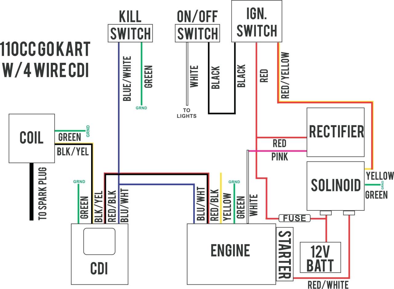
Chinese Cdi Box Wiring Diy Wiring Diagrams Electrical Wiring Diagram Motorcycle Wiring Trailer Wiring Diagram
The signal is a square wave but its only going to be present on one lead from the speed sensor.

700r4 Speed Sensor Wiring Diagram. FREE Shipping on orders over 25 shipped by Amazon. If you find 3 letters the transmission is made between 1986 1993. 700r4 speed sensor.
Testing either a 2 or 3 wire Hall Effect speed sensor is a relatively easy task and one that can save you quite a bit of money in the long run. 700r4 Speedometer Wiring Diagram. It gave all the different.
These guidelines will likely be easy to understand and apply. 700R4 Lockup Wiring Diagram Ny 9982 700r4 Lockup Wiring Tci As Well As 700r4 Lockup Wiring. It shows the components of the circuit as simplified.
Sep 16 Wiring AutoMeter electric speedometer to r4. I would assume one wire is the signal and is the other one a ground. T5 r4 Camaro Firebird Trans Am.
Drive and driven gears. Tci 700R4 Lockup Kit Wiring Diagram. There are 3 wires coming off the tranny.
It is meant to take action data flow or meting out amongst cut off units of function. Wiring Diagram September 18 2019 1545. Amazons Choice for gm 700r4 speed sensor.
Fuse holder connects to the lighted manual switchs bottom terminal providing the 12V power source. Vehicle Speed Sensor VSS T56 4L60E 4L80E Connector Pigtail for GM LT1 LT4 LS1 LS6 LS2 LS3 LS7 and many other VSS applications. If your trans has all its components for electronic it should be able to be used.
Installation Instructions TH-700R4 4L60 Transmission. About doing just the opposite of what you wanting to do. Most GM transmissions such as TH350 TH400 700R4 TH200 TH250s may use the AutoMeter 5291 speed sensor.
If a speed sensor is called a 2-pulse speed sensor it means the speed sensor puts out 2-pulses per cable revolution. 700r4 Transmission Speed Sensor Wiring Diagram wiring diagram is a simplified up to standard pictorial representation of an electrical circuit. Get it as soon as Fri Jan 7.
Likewise a 4-pulse speed sensor puts out 4000 pulses per mile. This is a 2 wire The AAW harness has 1 ground-yellow wire 1 signal-purple wirer4 Overdrive Wiring Diagram – A block diagram shows a higher level or organizational layout of in action units in a circuit or a device machine or hoard of these. Follow these easy steps.
I bought a 93 sr4 4L60E T5 Camaro Firebird Trans Am. Also does anybody know which is which. This will simply thread onto the transmission in place of where the cable used to go.
If this is the connector you have it is designed to plug into the 4000PPM VSS unit. 700r4 speed sensor wiring diagram. Does anybody know what the two wires are running into the speed sensor in the tailshaft of the 700r4.
Wiring Diagram comes with several easy to follow Wiring Diagram Directions. 1982-85 and some 1986-87 TH-700s controlled the Torque Converter Clutch. If you have the Autometer programmable speedo it can accept either PPM input I think it can accept pulse rates from 1000 to 20000PPM.
A 2-pulse speed sensor puts out 2000 pulses per mile. Most of them will be color-coded and can be easily drawn and. These sensors are self powered meaning the revolutions inside the case generate the signal needed to create movement in the speedometer.
Using a digital volt ohmmeter dvom measure the resistance ohmmeter function. 700r4 transmission speed sensor wiring diagram wiring diagram is a simplified up to standard pictorial representation of an electrical circuit. It is suitable for use behind engines producing up to 450 lb- ft of torque.
In 1991 the 700r4 transmission was replaced by the popular transmission 4L60. 700r4 Rebuild Tips Tricks Tools Truck Repair Rebuild Auto Repair If the resistance is 190 250 ohms the sensor is okay. These are necessary to make the lockup function work properly.
There are at least ten 10 different wiring arrangements that are found in the 700R4 transmission valve body. If not I can. R4 TCClockup wiring September 6th AM It looks to me like the trans was wired so it would lock up either when the pressure switch activates or.
700r4 Transmission Speed Sensor Wiring Diagram 16168625 to 700r4 Wiring for Lock Up Ih Parts America. Ok this what i have done i own a 89 s10 blazer 4×4 tbi v6 and removed the engine and all of the wiring harness ecm etc. The first element is emblem that indicate electric component in the circuit.
A circuit is generally composed by several components. An electrical speedometer reads pulses signal from the signal source. But its a 305 v8 tuned port motor from a camaro with a 700r4 trannyand i bought a brand new painless wiring loomit has a brown wire labeled vssbut i dont know where it gosi was told the wire gos behind the dash clusterbut i also heard there was a vss sensor on the tail of the trannyi have.
DOWNLOAD 700r4 Speedometer Wiring Diagram. Turbo 700R4 1982-1986 Turbo 700R4 1987-1992 TCI. The 700r4 transmission was not electronically controlled yet.
My 700r4 is electronic think there was an article on bow tie overdrives. Chopnchaneled Feb 26 2011. On the left is a 4-output vehicle speed buffer used on vehicles with electric speedometers.
Join us its free. 3 for an example wiring diagram. Another thing which you will find a circuit diagram would be lines.
Take time to draw your own diagram of the location of your valve body wiring terminal locations and connections. Description one 1 internal wiring harness one 1 external wiring harness one 1 vacuum switch. Im trying to wire up my Autometer speedometer and I need to know.
45 out of 5 stars 29. Written By admin Tuesday March 1 2022. Its meant to aid all the common consumer in creating a correct method.
Wire labeled Brake Switch in the dash group and the 5-position round connector in the tail section. Part Description Min Qty Price Qty. The center terminal of the switch is connected to the wire that leads down to the oil pressure switch on trans case.
There are just two things which are going to be found in almost any 700R4 Lockup Wiring Diagram. Its just that easy. Blog – electronic speedometer wiring diagram pulse generator or electonic speedometer pickup located in the transmission the vehicles PCM power train control module ECM.
REAL WORLD WIRING DIAGRAM The fuse holders connect to the vehicles fuse block. It was hydraulic pressure controlled with a TV cable which acted as a throttle position sensor to control the gear shifting. Ground the low-side signal wire and run the hi-side signal wire to the speedometer and calibrate.
This is a 2 wire The AAW harness has 1 ground-yellow wire 1 signal-purple wire. Tci 700R4 Lockup Kit Wiring Diagram. 700r4 Speedometer Plug Wiring Diagram.
Jump to Latest Follow. I pulled a connector to plug into the trans from the pull-a-part salvage. Lowest price in 30 days.
Speed Sensor Connector Wiring Harness Plug GM TPI TBI R4 T5 4L60E. P100 Inductive Proximity Sensor 18Mm 4B Braime Components Pdf 2 Wire Speed Sensor Wiring Diagram. 412 If you ARE going to use the lockup circuit then you MUST use a VSS vehicle speed sensor and the correct brake switch.
The BM TH-700R4 is a specially modified transmission intended for performance and heavy duty applications. Download 700r4 speedometer plug wiring diagram. This covers most small block Chevrolets and mild big blocks.

110cc Chinese Atv Wiring Diagram Schaferforcongressfo Motorcycle Wiring Pit Bike Trailer Wiring Diagram

Craftsman Riding Mower Electrical Diagram Wiring Diagram Craftsman Riding Lawn Mower I Need One For Craftsman Riding Lawn Mower Lawn Mower Riding Mower

Inspirational Wiring Diagram Pioneer Diagrams Digramssample Diagramimages Check More At Https Nostoc Pioneer Car Stereo Car Stereo Car Audio Installation

Unique Wiring Diagram For Chinese 110cc Atv Wiring Diagram Chinese Atv Wiring Diagrams Roketa 11 Motorcycle Wiring Electrical Diagram Electrical Wiring Diagram

45 Best Of 1994 Chevy Truck Brake Light Wiring Diagram Trailer Light Wiring Chevy Trucks Chevy 1500

Marine Power Inverter Wiring Diagram Trailer Wiring Diagram Diagram Wire

Honda Xl100 Motorcycle Complete Wiring Diagram All About Wiring Diagrams Electrical Wiring Diagram Motorcycle Paint Jobs Honda

Wire Harness Wiring Cdi Assembly For 50 70 90 110cc 125cc Atv Quad Coolster Go Kart Wish In 2022 Motorcycle Wiring 90cc Atv Chinese Scooters

Goodman Air Handler Wiring Diagram Inspirational Thermostat Wiring Air Handler Goodman Heat Pump

Lewmar Windlass Wiring Diagram Upgrade Windlass Power Wiring Of Lewmar Windlass Wiring Diagram With Windlass Wiring Diagram For Windlas Diagram Power Wire Wire

Wiring Diagram Ecu 2kd Ftv Throttle Systems Engineering Systems Engineering Crankshaft Position Sensor Ecu

700r4 Tci 20 A On Transmission Wiring Diagram Diagram Transmission House Wiring

How To Wire A Harley Davidson Coil New Motorcycle Wiring Harley Davidson Harley

50 Occupancy Sensors Lighting Wiring Diagram Af5u Light Switch Wiring Motion Sensor Security Lights
Cdi Wiring Diagram Motorcycle Wiring Kill Switch Electrical Wiring Diagram

Pin By Dwayne Camp On Basic Electrical Wiring Chevy Transmission Electrical Diagram Transmission

Harley Davidson Wiring Diagram Agnitum Me And At Harley Wiring Diagram Pocket Bike Sportster Home Electrical Wiring

Push Button Ignition Switch Wiring Diagram New Boat Wiring Kill Switch Electrical Wiring Diagram

Wiring Diagram For 110cc 4 Wheeler Fresh 110 Atv Wiring Help Atv Electrical Diagram 150cc Chinese Scooters