This video shows how to wire a 2 stage back to back both on nitrous system. Mode the nitrous controller will use output 1 and output 2 to control a single stage of nitrous.

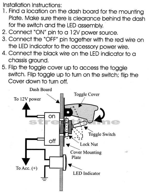
3 Toggle Switch Panel Translucent Blue In 2020 Toggle Switch Switch Paneling
Nitrous progression will resume when the controller is re activated.

Nitrous wiring diagram. Includes nitrous purge nitrous bottle heater and dedicated fuel system. Your 1 source for everything nitrous. Nitrous wiring diagram with transbrake.
Nitrous oxide install instructions directions. Single stage nos system with transbrake interrupt relay msd window switch and dynotune delay timer. Nitrous kits offer serious horsepower at the flip of a switch.
Intelligent nitrous progressive timer. Nitrous outlet universal dual stage wiring diagram company contact. Step by step pictures and diagrams to help you install your nitrous kit systems and components are the quickest and easiest way to get large horsepower increases with a minimum of engine modifications and expense.
The entire nitrous and 12 volt timer system is automatically reset 20 seconds after activation. The progressive nitrous timer system will wait at its present state if the activation signal is removed. When using this wiring strategy it is imperative that you select afr control in the max 5 software under tuning configuration input config setup controller.
Toggle navigation 254 848 4300 speak with a nitrous expert m f 8 30am 5 30pm cst. These wiring diagrams will help you wire up your nitrous system or nitrous accessory. Single stage nos system with transbrake interrupt relay.
By john heard last updated jan 4 2015. It is activated by applying 12volts. Nitrous outlet universal single stage wiring diagram company contact.
The stud labeled 2 is for the transbrake. Nitrous outlet stand alone purge system wiring diagram company contact. If you have any questions email email protected or call when wired in series with your nitrous system relay it will enable you plished by splicing into the trans brake solenoid wiring and using this power source to.

New Msd 7531 Wiring Diagram In 2020 Diagram About Me Blog Wire

0 10 Volt Dimming Wiring Diagram Di 2020 Diagram

How To Install A Nitrous Express Nitrous Kit Plate System On Your 1996 2004 Cobra Mach 1 Mustang Americanmuscle Nitrous Installation Mach 1

How To Wire An Nos Nitrous System Nitrous Bmw E34 System

The 2nd Generation Rx 7 Resource Msd Rx7 Generation

Draeger Pneumatic Linkage Of Oxygen And Nitrous Oxide Gas Flows Oxygen Ratio Controller Or Orc A No Respiratory Therapy Exam Respiratory Therapy Anesthesia

Http Www Bing Com Images Search Q Megasquirt Diagram Wire Engineering

Pro Flow Nitrous Oxide Systems Wilson Nitrous Wiring Diagram Wilson Get Free Image About Wiring Fire Extinguisher Vacuums Wire

Image Result For Nitrous Oxide Systems Diagrams Nitrous Suspension Systems System

Wiring Diagram Outlets Beautiful Wiring Diagram Outlets Splendid Line Wiring Diagram Help Signalsbrake Ligh House Wiring Wiring A Plug Home Electrical Wiring

Power Diverting Relay Schematic Diagram Car Audio Installation Automotive Repair Truck Lights

Wiring Diagram Cars Trucks Wiring Diagram Cars Trucks Truck Horn Wiring Wiring Diagrams Trailer Wiring Diagram Diagram Diagram Design

Making Nitrous Oxide In A Home Lab Nitrous Oxide Laughing Gas Nitrous

Gas Flow Control Needle Valve Datex Ohmeda A Oxygen B Nitrous Oxide Note The Secondary Pressure Regulator In The Nitrous Medical Studies Medical Dental

Image Result For Nitrous Oxide Systems Diagrams Nitrous Suspension Systems Diagram

Air Horn Wiring Diagram Horns Car Horn Relay

Wiring An Electric Fuel Pump Diagram Automotive Mechanic Electricity Car Mechanic


