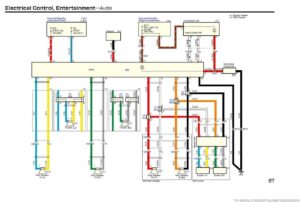
Diagram toyota 1nz fe wiring diagram toyota 1nz fe wiring diagram pdf toyota bb 1nz fe ecu pinout wiring diagram download by size handphone tablet desktop original size the wiring schematic you see here is the electrical wiring diagram of the toyota corolla. We have checked the contents of this manual for agreement with the hardware.
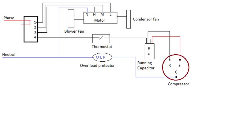
Ac Wiring Diagram Of Window Airconditioner Ac Wiring Thermostat Wiring Electrical Wiring Diagram
Analog modules 67 Analog input module SM 331.

6es73311kf020ab0 Wiring Diagram. Wiring Installing a smart dimmer switch into 3 gang box. Terminal assignment and block diagram of the SM 321. We have 5 2 wire 4-20mA signals and the rest of the inputs are spare.
Fuse box 04400 ignition. 15 Smart Switch Wiring Diagram. When i pulled the starter out completely and hoohed it direct to my charger it spun just fine but when it was connected and turned.
The STEP 7 online help supports you in the configuration and programming. 6es73311kf020ab0 wiring diagram. Resistance measurement with 2 3 and 4 wire connection the following connection possibilities also apply to silicon temperature sensors and ptcs.
Data sheet 6ES7331-1KF02-0AB0 SIMATIC S7-300 Analog input SM 331 Isolated 8 AI resolution 13 bits UIresistorPt100 NI100 NI1000 LG-NI1000 PTCKTY 66 ms. This manual contains notices you have to observe in order to ensure your personal safety as well as to prevent damage to Module SM in our example 6ESKFAB0. Properties wiring diagrams characteristics and technical specifications.
6es7331-1kf02-0ab0 Successor Description SIMATIC S7-300 Analog input SM 331 Isolated 8 AI resolution 13 bits UIresistorPt100 NI100 NI1000 LG-NI1000 PTCKTY 66 ms conversion time. Humbucker Wiring Diagram 3. System Manual and Getting Started describe in detail the configuration installation wiring and commissioning of the SIMATIC S7-1500 and ET 200MP systems.
Assemblies MTAs to adapt field wiring to ETM remote IO modules. DI 16 x 24VDC. 2-wire and 4-wire transducers for current measurement Figure 6-14 Block diagram and wiring diagram Note The interconnection between MANA and M- terminals 11 13 15 17 19 is not required when using.
Продолжение предыдущих объясненийВарианты использования многорежимного модуля аналогового ввода 6es7331. Wiring a 3-gang receptacle box is a relatively easy project that almost anyone can do successfully the first time. Suitable for switches and two three four-wire BEROs proximity switches.
AI 8 x 12 bit6ES7331-7KF02-0AB0 S7-300 Module data 372 Manual 022013 A5E00105505-08 Wiring. The connection diagram is printed on. This manual contains notices you have to observe in order to ensure your personal safety as well as to prevent damage to Module SM in our example 6ESKFAB0.
Next post 230 Volt Single Phase Wiring Diagram. SIMATIC S7-300 ANALOG INPUT SM 331 OPTICALLY ISOLATED 8 AI 13 BIT RESOLUTION UIRESISTANCEPT100 NI100 NI1000 LG-NI1000 PTC KTY 66 MS MODULE UPDATE 1 X 40 PIN. DI 16 x 24 VDC Status display green Channel number Backplane bus interface M 24 V Figure 3-4 Module View and Block Diagram of Digital Input Module SM 321.
6es7332 5hf00 0ab0 Wiring Diagram. Installation Channel Analog Output Module 6ES7 HFAB0 E-Stand 3 or higher. One j-box for Switch 1 wiring.
Spider box wiring diagram. Allied is the Distributor of Choice for Industrial Automation Control. Ad Wide Selection of PLCs HMIs from Siemens.
SIMATIC S7-300 S7-300 Automation System Module Data You will fing connection diagrams for your module along with all available signal modules for the S7-300 family. 6es7331 1kf02 0ab0 Wiring Diagram. Perfect Ford Alternator Wiring Diagram 85 Ford Bronco Wiring Diagram Wiring Diagram Rh 02 Ansolsolder Co 1982 Ford Chevy Trucks 1979 Chevy Truck 79 Chevy Truck.
A wiring diagram is a simple visual representation of the physical connections and physical layout of an electrical system or circuit. 03 Ford F150 Radio Wiring Diagram. Technical specifications of Analog input module 6ES7331-1KF02-0AB0.
6es7331 1kf02 0ab0 Wiring Diagram. The connection diagram is printed on. SIMATIC S7-300 ANALOG INPUT SM 331 OPT.
On example shown you can find out the type of a cable used to supply a feed to every particular circuit in a home the type and rating of circuit breakers devices supposed to protect your installation from overload or short current. Hi new to Siemens so please be gentleCurrently trying to commission a Siemnes PLC and analogue card as above can some please tell me if the wiring diagram is correct. Previous post 88 Chevy Truck Fuel Pump Wiring Diagram.
The connection diagram is printed on. Documentation guide Analog Input Module AI 8xUI HF 6ES75317NF00- -0AB0 8 Manual 092016 A5E36649087-AB General information The function manuals contain detailed descriptions on general topics regarding the SIMATIC. Browse Our Site Today.
Article Number Market Facing Number 6ES7331-1KF02-0AB0. Product data sheet 6ES7331-1KF02-0AB0 Author. Product data sheet MLFBS.
ISOL234 WIRE 8AI RESISTANCE PT1002001000 NI1001202005001000 CU10 PLUS CHARACTERISTICS ACCORDING TO GOST STANDARD 16 INTERN 24 BIT 50MS 1 X 40 PIN Supply voltage Load voltage L Rated value DC 24 V Reverse polarity protection Yes Input current. From backplane bus 5 V DC max. Profibus Connector 6es7331 1kf02 0ab0.
Data sheet 6ES7331-1KF02-0AB0 SIMATIC S7-300 Analog input SM 331 Isolated 8 AI resolution 13 bits UIresistorPt100 NI100 NI1000 LG-NI1000 PTCKTY 66 ms. We have 5 2 wire 4 20ma signals and the rest of the inputs are spare. Device information Manuals contain a compact description of the module-specific information such as.
Siemens AG Automation and Drives Subject. Download 6es7331 1kf02 0ab0 wiring diagram. Specifically designed MTA descriptions and diagrams.
Ad Global Leader In Industrial Supply And Repair Services. 3 gang light switch wiring diagram. SIMATIC S7-300 Analog input SM 331 Isolated 8 AI resolution 13 bits UIresistorPt100 NI100 NI1000 LG-NI1000 PTCKTY 66.

110cc Chinese Atv Wiring Diagram Schaferforcongressfo Motorcycle Wiring Pit Bike Trailer Wiring Diagram

Unique Wiring Diagram For Chinese 110cc Atv Wiring Diagram Chinese Atv Wiring Diagrams Roketa 11 Motorcycle Wiring Electrical Diagram Electrical Wiring Diagram

Unique Wiring Diagram For Chinese 110cc Atv Wiring Diagram Chinese Atv Wiring Diagrams Roketa 11 Motorcycle Wiring Electrical Diagram Electrical Wiring Diagram

Marine Power Inverter Wiring Diagram Trailer Wiring Diagram Diagram Wire

Air Conditioner C S R Wiring Diagram Compressor Start Full Wiring Fully4 Air Conditioner Maintenance Refrigeration And Air Conditioning Hvac Air Conditioning

Lewmar Windlass Wiring Diagram Upgrade Windlass Power Wiring Of Lewmar Windlass Wiring Diagram With Windlass Wiring Diagram For Windlas Diagram Power Wire Wire

Honda Xl100 Motorcycle Complete Wiring Diagram All About Wiring Diagrams Electrical Wiring Diagram Motorcycle Paint Jobs Honda

Wiper Switch Wiring Diagram Best Of Diagram Stereo Idea Trailer Wiring Diagram

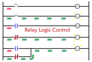
30 Unique Headlight Relay Wiring Diagram Electrical Wiring Diagram Electrical Circuit Diagram Relay

16 Motorcycle Horn Relay Diagram Car Horn Motorcycle Wiring Electrical Diagram

Push Button Ignition Switch Wiring Diagram New Boat Wiring Kill Switch Electrical Wiring Diagram

Harley Davidson Wiring Diagram Agnitum Me And At Harley Wiring Diagram Pocket Bike Sportster Home Electrical Wiring
Domestic Refrigerator Wiring Electrical Wiring Diagram Circuit Diagram Refrigeration And Air Conditioning

Split Ac Full Electric Wiring Diagram Fully4world Fully4world Air Conditioning System Design Refrigeration And Air Conditioning Hvac Air Conditioning

Bosch Relay Wiring Diagram Elegant Electrical Circuit Diagram Circuit Diagram Electrical Diagram

Unique Yamaha Moto 4 Wiring Diagram Yamaha Golf Carts Electric Golf Cart Diagram

Wiring Diagram Ac Generator Valid Modern Dc Wiring Gallery Circuit Diagram Electrical Circuit Diagram Diagram

Unique Single Phase Capacitor Start Capacitor Run Motor Wiring Diagram Electrical Wiring Diagram Electrical Circuit Diagram Capacitor

5 Pin Wiring Diagram Electrical Diagram Electrical Circuit Diagram Trailer Wiring Diagram