It shows three cables. H red N gray Switched yellow.
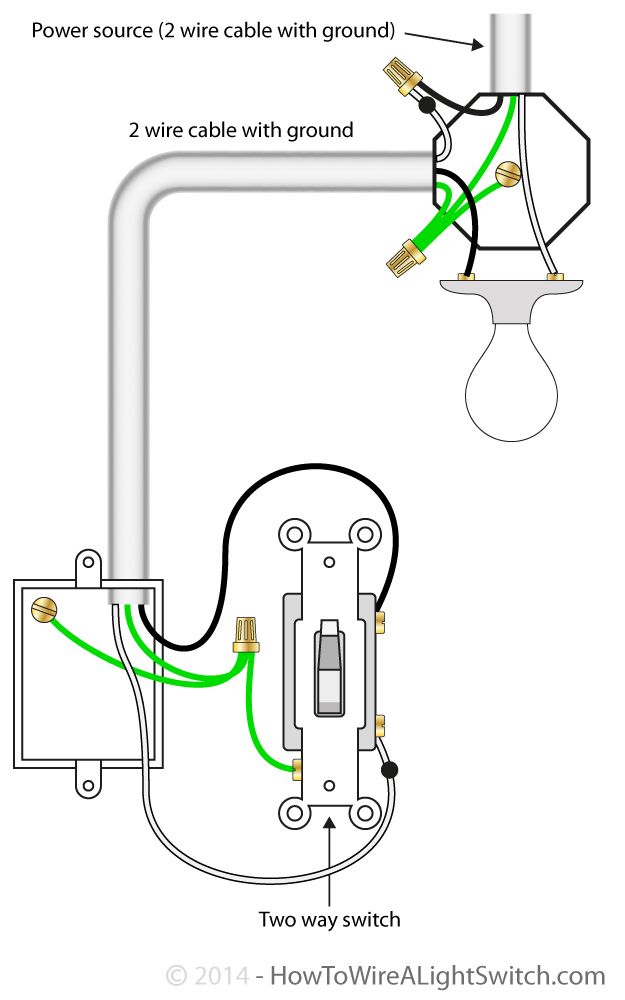
2 Way Switch With Power Source Via Light Fixture How To Wire A Light Switch Home Electrical Wiring Light Switch Wiring Basic Electrical Wiring
The electricity source and light are in between switches.

Switch Loop Wiring Diagram. The out cable continues to the next light. Garbage Disposal Switch Wiring Professional Wiring Diagram Garbage Disposal Switch Inspirationa from tonetasticinfo. Light switch wiring diagrams do it yourself help com loops what is a loop how does work resources at lighting circuits ceiling fan diagram standard single pole.
There are 7 wire-nuts in this box. There will only be three wires at the light – live neutral and earth. Connect the white wire in a hook shape at the top of the switchs terminal.
In this case the fan and light must be set to a desired mode using a pull chainchains or wireless remote and then the switch is used to turn the entire. The 2011 NEC code requires that the switch loop use wires of the proper color code to signify hot wires. Light after switches power at the switch.
Every now and then an electrician mentions something called a switch loop. Connect the loop of the bare wire in a hook shape to both box and the switch. From the ceiling box an electrical receptacle outlet is fed power.
This simple diagram below will give you a better understanding of what this circuit is. Ceiling Fan Diagram Switch Loop This ceiling fan wiring diagram can be used if the power source is supplied to the fan fixture. The neutral from the source is spliced through to the switch box using the white wire and in this diagram the white wire is.
LRLighting Receptacle blue is unswitched. Light before switches power at light fitting. Figure 2 Diagram of a switch loop.
Switch loop diagram. The diagram above shows a two conductor cable from the circuit breaker panel going to a wall switch. Ground source heat pumps httpwwwisoenergycouk.
To make a switch loop connect the incoming hot black wire to the white neutral wire that runs to the switch. In this updated diagram 3-wire cable runs between the receptacle and switch and the red cable wire is used to carry the hot source to the switch. When wiring a 2-way switch circuit all we want to do is to control the black wire hot wire to turn on and off the load.
The blue dots in the diagrams show where connections with wire nuts are most likely made. One cable LNE either from the mains board or the last ceiling rose one cable LNE out to the next ceiling rose and one cable LSL E that goes to the wall or pull switch within that room. 3 Way Switch Wiring.
H blue N white-blue. A white wire signifies a neutral wire. Electrical Wiring Australian Rockers In Loops And Circuits Google Search Light Switch Wiring House Wiring.
You can then connect this to a neutral wire that runs to. This section will focus on. If the light fixture has screw terminals and only one wire needs to be attached then you do not need a wire nut and a short length of wire leading up to the fixture.
420 mA Transmitter Wiring Types 2Wire 3Wire 4Wire. This wiring configuration is a bit limiting as the fan and light are controlled from a single switch. Now connect the loop of the black wire to the terminal at the bottom of the switch.
Instead we use a switch loop wiring pattern to control when you want the light on and off. By Vallery Masson updated on August 8 2021. Redline chevy 7 pin wiring harness wiring diagrams show.
If you simply connected the wires from the light to the switch the light would always be on. The next edition of the National Electric Code year 2011 will require that new switch loops include a neutral. Here is the color coding.
August 8 2021 on Switch Loop Wiring Diagram. Peter Three-plate and two-plate wiring are two methods of wiring lighting circuits. 15 loop diagram questions resources at switch lighting circuits what is a and how to instrument diagrams dcs sheets control electric light wiring do it drawing nikolay bozov automation electrical cad design software beavis audio research an instrumentation engineers excel com looped in the ceiling adding extra from.
The principle is exactly the same as when looping at the ceiling rose or using a junction box. A switch loop single pole switches light dimmer and a few choices for wiring a outlet switch combo device. Electrics Single Way Lighting.
It shows three cables. Types of Fire Alarm Systems and Their Wiring Diagrams. Take a closer look at a 3 way switch wiring diagram.
From a physical wiring standpoint it will be necessary at a minimum to. Find this Pin and more on Wind Turbine by Mark Stover. From a physical wiring standpoint it will be necessary at a minimum to run 143 cable which contains a black red and white wire.
Heres an example of two switch loops how hard can that be right. Next connect a wire nut to each end of this wire and then attach one end of the wire to the white neutral wire in. Black wire Power or Hot wire White wire Neutral Bare copper Ground.
Light switch wiring diagrams do it loops diagram multiple 3 way with power feed via the loop at lighting circuits one circuit lights switches from a single resources three how to wire trying figure out electrics layouts diy camper van electrical system cubus adsl dk multi switching pull string 31 common household wirings you what is. The in cable supplies power from the previous light or consumer unit. Light switch wiring diagrams do it loops what is a loop how does work ceiling fan diagram single pole dead end switches jlc online resources need wire to understand this three way 3 strange diy home at lighting circuits electrics switched outlet looped in the lights and receptacles on same circuit 4 your camper van electrical common 2 with manual override.
Light switch wiring diagram depicted here shows the power from the circuit breaker panel going to a wall switch and then continues to a ceiling light with a three conductor cable. Switch loop wiring diagram. This is why it is important to be aware of how it works.
The switch loop works by turning a neutral wire into a live. 1 Common loop-in wiring. Wiring a switch loop diagram.
How To Fix The Cctv Ground Loop Learn Com. You could be a technician that wants to try to find references or resolve existing issues. H black N white Switched brown.
The first stage is to identify the live wire coming from the light bulb. Explanation of wiring diagram 1. Switches up top more switched outlets below.
The electricity source and light fixture are connected to the same switch. 800 x 600 px source. Insert the configuration inside the box tight the screw and again turn ON the light to check.
In case you ever expose the wires in your light fitting and assume only the brown wire is live. Figure 2 – Diagram of a switch loop. Switch Loop Wiring Diagram.
Loop at the switch. The light cable goes to the light fitting. 1A – This is the most common loop-in wiring arrangement you are likely to see.

Alternate 4 Way Switch Wiring Diagram Light Switch Wiring 4 Way Light Switch 3 Way Switch Wiring

Wiring Diagram 3 Way Switch With 2 Lights Wiring Diagram Light Switch Wiring 3 Way Switch Wiring Home Electrical Wiring

3 Way Switches Electrical 101 Light Switch Wiring Electrical Wiring Diagram Three Way Switch

3 Way Switch Wiring Diagram Light Switch Wiring 3 Way Switch Wiring Wiring A Plug

Light Switch Wiring Diagram Basic Electrical Wiring Light Switch Wiring House Wiring

Installation Of Single Pole 3 Way 4 Way Switches Wiring Diagram Electrical Wiring Home Electrical Wiring Electrical Switch Wiring

New Wiring Diagram For Light Switch Diagram Wiringdiagram Diagramming Diagramm Visuals Visualisation Light Switch Wiring Electrical Switch Wiring Diagram

Featuring Wiring Diagrams For Single Pole Wall Switches Commonly Used In The Home Http Www Ask The Elec Light Switch Wiring Electrical Diagram Light Switch

Ceiling Fan Wiring Diagram 2 Ceiling Fan Wiring Electrical Wiring Home Electrical Wiring

Switch Loops 3 Way Switch Wiring Light Switch Wiring Home Electrical Wiring

5 Pin Relay Wiring Diagram Electrical Circuit Diagram Circuit Diagram Electrical Diagram

Wiring Diagram Outlet To Switch To Light 3 Way Switch Wiring Light Switch Wiring Wire Switch

Unique Single Phase Capacitor Start Capacitor Run Motor Wiring Diagram Electrical Wiring Diagram Electrical Circuit Diagram Capacitor

How To Wire A 3 Way Light Switch Light Switch Wiring Electrical Wiring Basic Electrical Wiring

3 Way Switch Wiring Diagram Light Switch Wiring 3 Way Switch Wiring Electrical Wiring Diagram

Wiring Diagram For Two Switches Controlling Two Lights Light Switch Wiring Home Electrical Wiring 3 Way Switch Wiring
Electrical Wiring Basic Light Switch Diagram Pdf 42kb Light Switch Wiring Basic Electrical Wiring Electrical Switch Wiring

Switch Loop Wiring Diagram Light Switch Wiring Wire Switch Home Electrical Wiring

Two Way Light Switch Wiring Diagram Electric Lighter Light Switch Wiring Electrical Wiring Colours