L3 circuit breaker stop start m ot t1 t2 t3 m m solid state overload relay 1ct m m motor 3ct to 120 v separate control ot is a switch that opens. It shows the components of the circuit as simplified shapes and the power as well as signal connections between the devices.

Wiring Diagram For A Circuit Breaker Box Electrical Wiring Basic Electrical Wiring Home Electrical Wiring
Installing a circuit breaker on a 3 phase or dc generator is a cinch.

Circuit breaker wiring diagram. Variety of square d breaker box wiring diagram. This kind of circuit is used for dishwashers whirlpool spas and other locations where water contact is likely. Find a diagram of a breaker box online before getting started.
If at any point you feel unsure of what you re doing consider getting a professional electrician to do this job for you. Just take a look at the wiring diagrams available for download here. Dc generator wiring diagram.
Circuit breaker wiring diagrams. On afci or gfci breakers this circuit wire will be attached to the terminal marked load power or black finally for afci or gfci breakers attach the breaker s coiled white pigtail wire to the neutral bus bar in the panel. Circuit breakers made by square d murray ite sylvania westinghouse etc.
The wiring into a breaker must correspond to its amperage. A wiring diagram is a streamlined standard pictorial depiction of an electric circuit. Helpful 0 not helpful 0.
Wiring a four poles rcbo or gfci circuit breaker three phase rccb wiring the three phase wiring for gfci or rcd rccb or rcbo wiring diagram shows the three lines l1 l2 and l3 and neutral has been connected as input to the rccb from main board followed by mcb i e. This diagram illustrates wiring for a circuit breaker with a built in ground fault circuit interrupter or gfci. Twelve gauge wire suits 15 to 20 amp breakers.
Are to be installed in panels made by the same breaker manufacturer. 8 gauge wire goes with 40 or 60 amp two pole breakers. 3 phase ac wiring diagram.
Wiring a gfci circuit breaker. A typical wiring diagram with dc control for a westinghouse dhp is shown in the figure below. This 20 amp 120 volt breaker is a form of gfci that can be installed at the circuit source.
Wiring diagram book a1 15 b1 b2 16 18 b3 a2 b1 b3 15 supply voltage 16 18 l m h 2 levels b2 l1 f u 1 460 v f u 2 l2 l3 gnd h1 h3 h2 h4 f u 3 x1a f u 4 f u 5 x2a r power on optional x1 x2115 v. With all circuit wires connected the circuit breaker can be snapped into place into its panel slot. This will help you ensure you are working with the correct wires and bus bars as you wire a breaker circuit.
We will be using this simple diagram to discuss the components involved with the electrical operating sequence of a circuit breaker. Do not make the mistake of trying to install a square d or other manufacturer circuit breaker into a different manufacturer s panel.

How To Wire Mccb Circuit Breakers 3 Pole And 4 Pole Teknologi

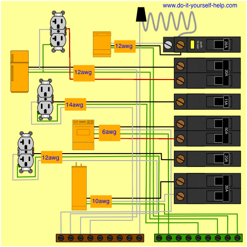
Circuit Breaker Wiring Diagrams Do It Yourself Help Com Electrical Wiring Home Electrical Wiring Diy Electrical

Wiring Diagram Circuit Breaker Blurts Me Rh Blurts Me 4 Pole Breaker Wiring Diagram Breaker Box Wiring Dia Diagram Electrical Wiring Diagram Electrical Diagram

How To Wire A Gfci Breaker In 2020 Gfci Hot Tub Controls Breakers

Basic House Wiring Home Electrical Wiring Basic Electrical Wiring House Wiring

Air Circuit Breaker Power Engineering Electrical Wiring Electrical Breakers

Circuit Breaker Wiring Diagrams Do It Yourself Help Com Electrical Wiring Outlet Wiring Home Electrical Wiring

Wiring Diagram For A New Code Compliant 30 Amp 240 Volt Circuit Breaker Metal Electrical Box Diy Electrical Circuit

Wiring Diagram For A 30 Amp 240 Volt Circuit Breaker Home Electrical Wiring Electrical Wiring Electrical Wiring Outlets

Wiring Diagram For A 30 Amp 240 Volt Circuit Breaker Home Electrical Wiring Electrical Wiring Electrical Wiring Outlets

What To Do If An Electrical Breaker Keeps Tripping In Your Home Home Electrical Wiring Electrical Breakers Electrical Panel Wiring

A Shunt Trip Breaker Wiring Diagram With Emergency Switch Or Kill Switch A Complete Diagram Of Mccb Shunt Trip Breaker Diagram Diagram Electrical Diagram Trip

Circuit Breaker Wiring Diagrams Do It Yourself Help Com Home Electrical Wiring Electrical Wiring Electrical System

Ground Fault Circuit Breaker And Electrical Outlet Wiring Diagram Png 1225 879 Circuit Breaker Panel Breaker Panel Electrical Breakers

Circuit Breaker Wiring Diagrams Home Electrical Wiring Diy Electrical Electrical Breakers

How To Wire And Install A Breaker Box Electrical 4u House Wiring Home Electrical Wiring Electrical Wiring

Awesome Wiring Diagram Potentiometer Diagrams Digramssample Diagramimages Wiringdiagramsample Wiringd Electrical Wiring Diagram Diagram Electrical Diagram

Wiring Diagram For A 15 Amp 120 Volt Isolated Ground Circuit Breaker Panel Home Electrical Wiring Diy Electrical

Circuit Breaker Wiring Diagrams Do It Yourself Help Com Home Electrical Wiring Electrical Wiring Basic Electrical Wiring

