Turn the power back on at the circuit-breaker panel. The following wiring shows an ordinary outlet has been wired and protected through single phase single pole GFCI circuit breaker.
Gfci Outlet Wiring Diagram Electrical Wiring Diagram Outlet Wiring Home Electrical Wiring
In this GFCI outlet wiring and installation diagram the combo switch outlet SPST single way switch and ordinary outlet is connected to the load side of GFCI.

Single Gfci Outlet Wiring Diagram. Wiring a gfci receptacle is a little more complicated than hooking up a regular outlet but easily learned once explained. Single gfci wiring diagram Whats Wiring Diagram. This GFI Outlet comes with yellow tape over the LOAD side.
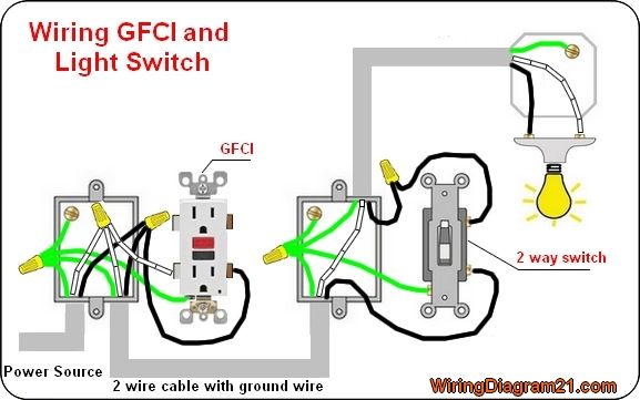
POWER SOURCE 2-Wire Romex with Ground ie. Cable Wires LINE cable. This diagram illustrates wiring a GFCI receptacle and light switch in the same outlet box a common arrangement in a bathroom with limited space.
Collection of ground fault receptacle wiring diagram. With this kind of an illustrative guide you are going to have the ability to troubleshoot avoid and total your projects easily. Wiring a GFCI Outlet and a Light Switch.
Switch and in the same box quora procedure diagram explained etechnog electrician explains half hot dengarden switches gfci connection install plug socket socketsandswitches board. GFCI Outlet Wiring Diagram House Electrical Wiring Diagram. This gfi outlet comes with yellow tape over the load side.
Test the GFCI by pressing the Black Test button on the outlet. You can wire a single GFCI with multiple outlets using the 2 wires cables multiple outlets and GFCI. Wiring Diagram Line We are make source the schematics wiring diagrams and technical photos.
Wiring Diagram For A Single Outlet Wiring Diagram Line Wiring Diagram. It means all the connected loads to the load terminals of GFCI are protected. See Diagram A.
Youll have to use that single GFCI as the source and then connecting the rest of the outlets using the same load and line terminals. This diagram illustrates wiring a gfci receptacle and light switch in the same outlet box a common arrangement in a bathroom with limited space. This example of wiring a single GFCI receptacle outlet shows a outlet box with one pair of wires form a 2-wre cable with a ground wire.
Gfci outlet with switch wiring diagram How to Install A Gfci with 4 Wires Luxury Wiring Diagrams for A Gfci Outlet Do. 17 single gfci wiring. All countertop receptacle outlets must be protected by a GFCI device installed at the outlet or by GFCI circuit breakers.
The builtin white wire in the ground fault circuit interrupter circuit breaker should be directly connected to the incoming supply neutral bar in the home mains distribution board or it will not work otherwise. Connect the LINE cables bare copper or GREEN wire directly to the grounding lead on the GFCI receptacle. In this example the GFI protection serves this outlet location only.
40 Lovely Install Gfci with 4 Wires. A wiring diagram is a kind of schematic which uses abstract pictorial symbols to exhibit all of the interconnections of components inside a system. At times the cables will cross.
The source hot wire is spliced with one of the switch wires and the other switch wire is connected to the hot LINE terminal on the device. Gfci outlet with switch wiring diagram Youll need a comprehensive professional and easy to comprehend Wiring Diagram. Injunction of 2 wires is generally indicated by black dot to the intersection of 2 lines.
Wiring Diagram for a Switched GFCI Combo Outlet. The National Electrical Code requires. The source neutral is connected the LINE neutral terminal.
Replace the receptacle screw it back into the box and attach the cover plate. Fully explained wiring instructions complete with a picture series of an installation and wiring diagrams can be found here in the GFI and Light Switch area here in this website. To wire a gfci circuit breaker see this link and wire a gfci switch combo at this link.
Unscrew the terminal screws of the new GFCI outlet until they are difficult to turn. Connect the ends of these wires to the LINE cables bare copper or green wire using a wire connector. With this kind of an illustrative guide you are going to have the ability to troubleshoot avoid and total your projects easily.
Wiring for a switch and gfci receptacle in the same box is also shown. Wiring for a switch and gfci receptacle in the same box is also shown. Be a hero and install it right the first time.
Wiring diagrams are made up of 2 points. Wiring a gfci outlet and a light switch. Just click the Wiring Diagrams Wiring a GFCI Outlet with a Switch How to Wire a GFCI Outlet with a Switch There are a few different methods that are used to.
17 single gfci wiring diagram posted on march 18 2020 august 18 2020 by gary l. Wiring diagram for a gfci and multiple duplex receptacles In the event of a ground fault a GFCI will trip and quickly stop the flow of electricity to prevent serious injury. Wiring a gfci outlet with diagrams pro tool reviews how to wire multiple outlets step by guide install dengarden do it yourself help com receptacle diy family handyman upgrading 2 g new run light circuit from quora what is and where required leviton 15 amp self test smartlockpro slim duplex white r72 gfnt1 0rw the connection diagram etechnog.
This section of the circuit then is an example of wiring in series. Turn the power OFF and check the wire connections against the appropriate wiring diagram in step 7A or 7B. Delivers power from the service panel breaker panel or fuse box to the GFCI.
Below mentioned wiring diagram shows a single GFCI outlet connected with the multiple outlets. The wires attaching to the GFI Outlet connect to the LINE Side. According to previous the traces at a Gfci Outlet With Switch Wiring Diagram represents wires.
In the first diagram the single way switch and light bulb is connected to the load terminal of gfci. Wiring Diagram Sheets Detail. Gfci outlet with switch wiring diagram Youll need a comprehensive professional and easy to comprehend Wiring Diagram.
However it does not imply link between the cables. Connect the grounding wire only if there is a grounding wire. GFCI receptacle For a box with a grounding terminal diagram shown above.
Gfci outlet with switch wiring diagram How to Install A Gfci with 4 Wires Luxury Wiring Diagrams for A Gfci Outlet Do. Connect a 6-inch bare copper or green 12 or 14 AWG wire to the grounding terminal on the GFCI. In the first diagram the single way switch and light bulb is connected to the load terminal of gfci.
The black wire connects to the GFCI HOT lead. Connect the bare ground wire to the green Ground screw. For a box with no grounding terminal diagram not shown.
In this diagram the switch built into the combo device is wired to control the gfci outlet itself. Also connect a similar wire to the grounding terminal on the box. In this GFCI outlet wiring and installation diagram the combo switch outlet SPST single way switch and ordinary outlet is connected to the load side of GFCI.
The toggle switch in the combo switch outlet controls the first light bulb while the single way. Wiring ground fault outlet diagram. GFCI Outlet Wiring Diagram.
Wiring a gfci outlet with a light switch. There will be primary lines which are represented by L1 L2 L3 and so on. Plug a clock radio or light into the outlet.
The white wire connects to the GFCI WHITE lead. The wires attaching to the gfi outlet connect to the line side. You can also learn about wiring gfci outlets in the following 7 steps.
Leviton W 15 Amp Volt Receptacle 20 Amp Feed-Through.

Combo Switch Fan Light 110v To 2 Gang Timer Switch 2 110v Light Switch Wiring Basic Electrical Wiring Outlet Wiring

Change Half Switched Outlet Basic Electrical Wiring Electricity Home Electrical Wiring

Wiring Diagram For A 30 Amp 240 Volt Outlet For Clothes Dryer Outlet Wiring Electric Dryers Electrical Plug Wiring

Wiring Diagram For A New Code Compliant 30 Amp 240 Volt Circuit Breaker Metal Electrical Box Home Electrical Wiring Diy Electrical

Gfci Outlet Wiring Outlet Wiring Basic Electrical Wiring Gfci

Double Outlet Box Wiring Diagram In The Middle Of A Run In One Box Outlet Wiring Electrical Wiring Electrical Wiring Outlets

Wiring Diagrams Multiple Receptacle Outlets Outlet Wiring Home Electrical Wiring Electrical Outlets

Electrical Wiring Diagram Home Electrical Wiring Electrical Wiring Basic Electrical Wiring

Understanding 240v Ac Power For Heavy Duty Power Tools Make Outlet Wiring Ac Plug Trailer Wiring Diagram

Wiring Diagram For A Gfci Outlet And Light Switch In The Same Box Outlet Wiring Electrical Wiring Light Switch Wiring

Gfci Outlet Wiring Diagram Basic Electrical Wiring Home Electrical Wiring Electrical Wiring Diagram

Multiple Gfci Outlet Wiring Diagram Outlet Wiring Electrical Wiring Gfci

Wiring Switches And Outlets Gfci Outlet Wiring Wire Switch

Bosch Relay Wiring Diagram Elegant Electrical Circuit Diagram Circuit Diagram Electrical Diagram

Wiring Diagram To Add A New Outlet Off A Light Fixture Home Electrical Wiring Electrical Wiring House Wiring

Wiring Diagram For A Switched Gfci Outlet Outlet Wiring Wiring Outlets Home Electrical Wiring

Understanding 240v Ac Power For Heavy Duty Power Tools Make Electrical Plug Wiring Outlet Wiring Electrical Wiring Diagram
Pin On Single Phase Wiring

Simple Home Electrical Wiring Diagrams Electrical Wiring Diagram Home Electrical Wiring Outlet Wiring