From our pump selection guide to pump diagrams and specifications you can easily access all the technical information you need at the Grundfos Product Center. Attach incoming grounding wire to either of the green grounding screws.
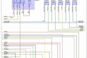
Fresh Wiring Diagram Inverter Diagrams Digramssample Diagramimages Wiringdiagramsample Wiringdiagram Thermostat Wiring Ac Wiring Electrical Wiring Diagram
Stainless steel and bronze body pumps Comparable Grundfos replacement options Taco pumps Primary model s Page Conn.

Grundfos Pump Wiring Diagram. 4 Wiring diagram for 115 V and 230 V multi-speed pumps. 511 Single-speed pump wiring 1. GRUNDFOS INSRUIONS UPZP-1 Single-zone pump control Installation and 5 Wiring N English US Optional for 3-wire thermostat W R O M N Boiler.
A Beginners Guide to Circuit Diagrams. Describe Grundfos CM pumps. The wiring diagram is located in the terminal box cover.
Wiring ease with 120 VAC ground and low-voltage screw terminal inputs. 31 Applications The Grundfos MAGNA3 is designed for circulating liquids in the following systems. 3 Wiring diagram for all 115 V and 230 V single-speed pumps Fig.
Wiring diagram for grundfos pump. Heating systems domestic hot-water systems air-conditioning and cooling systems. Grundfos submersible pump wiring diagram Whats Wiring Diagram.
Wiring diagram for grundfos pump – Grundfos Pumps Grundfos CH4-50 11. Variety of grundfos pump wiring diagram. The alarm Grundfos Conlift1 LS is a small compact lifting station with evaporators.
Click on the image to enlarge and then save it to your computer by right clicking on the image. 55 Wiring diagram for system connections CU 401 5 56 Wiring diagram for IO 403 connections example 6 57 Wiring diagram for two pumps via IO 401 module 7 58 Wiring diagram for SM 111 with IO 111 module 8 59 Use of inputs when connecting multiple units 9 510 SM 111 and IO 111 10 511 Combi alarms 12 512 User-defined IO 12 513 Radio. You can type in the product name and press search to find matches.
Hi I am going to change my Present Grundfos UPS 15-50 pump to the Grundfos Alpha L2 15-50 pump I have query regarding the wiring is the pump wired to any of the heating controls or just to the mains my intention was to just put a 13 amp plug on the lead and plug it into a standard 13 amp switched socket. 3 Wiring diagram The motor is. Grundfos SQFlex Solar Water Pump Wiring Diagram.
Additional features UPZCP-3 -4 -6 Grundfos UPZCP-3 -4 -6 zone controls offer these additional features. Grundfos pump wiring diagram Grundfos Pump Wiring Diagram Awesome 177 Best Motor Pinterest. Type Pump length UP 15-10B5 28 12 sweat 5 003-BC 12 sweat 4-1332.
Type Pump length Model Conn. Click here to view print or download the Grundfos SQFlex Solar Water Pump Wiring Diagrampdf. Grundfos sl series wiring diagrams pdf seg booster pump tommy o r i e aqqe f a n 98923273 axeon mq user manual instructions up zv diagram for centre guide sqflex renewable energy.
Competitor cross-reference Open systems. A wiring diagram is a kind of schematic which uses abstract pictorial symbols to show all of the interconnections of components in a very system. Grundfos pump wiring diagram Grundfos Pump Wiring Diagram Best Central Heating Controls and Zoning Diywiki.
Ground source heat pump systems. Grundfos provides no guarantee as to the accuracy of competitor information listed herein. A first look at the circuit diagram might be confusing but if read a subway map search for schematics.
At the Grundfos Product Center you can quickly and easily find pump installation guides pump manuals and all the technical data you need to keep your system working its best. Front-facing LEDs on the front. Grundfos UPZCP-3 -4 -6 zone controls offer these.
Grundfos circulating pump wiring diagram also included here is the wiring schematic for the relay i m particularly concerned about having two transformers in the same system. 3 Wiring diagram for all 115 V and 230 V single-speed pumps. Grundfos motors types MG 71 and MG 80 as well as MG 90 15 kW 2-pole for supply voltages up to and including 440 V.
Side-mounted terminal connections for ease of wiring and installation. Sections give the Before installing the pump check that the pump type and parts are as. Grundfos Pump Wiring Diagram.
Insert black conductor into terminal L position. Pumps are adapted from Grundfos present 4 SP range 16S 25S 40S and 60S. Connect the whitewhite electrical leads from the circulator pump to the incoming power leads with wire nuts or other approved connectors.
Go to Grundfos Product Center. The Conlift is suitable for the pumping of condensate. Wiring diagrams 18 13 1 symbols used in the wiring diagrams 18.
Applies only to three-phase Grundfos motors marked IE2 or IE3. Looking for more interactive technical content. The positive displacement helical pump ends are.
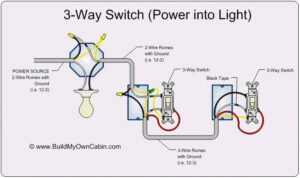
Home Decorating Style 2022 for Grundfos Pump Wiring Diagram you can see Grundfos Pump Wiring Diagram and more pictures for Home Interior. October 11 2021 1. Wiring diagrams zone valve controllers.
Wiring diagram for grundfos pump grundfos pumps grundfos ch4 50 11. Grundfos Pump Wiring Diagram Grundfos Submersible Sewage Pump Cast Iron Se1 50 65 30 2 50d B 3 Kw 400v 3 50. Or if you have the product number you can search by that as well.
511 Single speed and multi-speed pump wiring 1. The pump can also be used in the following systems. Insert white conductor into terminal N position.
The terminal box of single-speed motors normally contains six winding terminals and at least one earth. Pump exercise selectable for 72 hours or 14 days. Insert grounding conductor into terminal position.
Once you enter Grundfos Product Center you will see a menu with four coloured categories at the top. Learn how to properly connect the wiring on a Grundfos CU 301 control to an SQE submersible waterwell pump. Grundfos Pump Wiring Diagram.
GRUNDFOS circulators Wiring diagram for V and V multi-speed pumps. Applies only to water pumps marked with the minimum efficiency Wiring diagramGrundfos offers a. These pumps are used when lower heads and higher flow rates are required.
Before installing the pump check that the pump type and parts are as Install the pump so that inspection maintenance and service can. The desired head can be set on the pump control panel. Search by product name or number.

Franklin Electric Control Box Wiring Diagram Well Pump Pressure Switch Submersible Well Pump Well Pump

Submersible Pump Control Box Wiring Diagram For 3 Wire Single Phase Submersible Pump Submersible Well Pump Well Pump

Installing Turn Signals Motorcycle Wiring Electrical Diagram Electrical Wiring Diagram

Unique Wiring Diagram For Chinese 110cc Atv Wiring Diagram Chinese Atv Wiring Diagrams Roketa 11 Motorcycle Wiring Electrical Diagram Electrical Wiring Diagram

Ez Go Golf Cart Wiring Diagram Gas Engine Free Wiring Diagram Electrical Wiring Diagram Electrical Diagram Ezgo Golf Cart

Walnut Innovations Automatic Water Level Controller Water Level Sensors For Single Ph Submersibles Operated Submersible Pump Submersible Well Pump Sump Pump

Best Relay Wiring Diagram 5 Pin Bosch Electrical Circuit Diagram Circuit Diagram Electrical Diagram

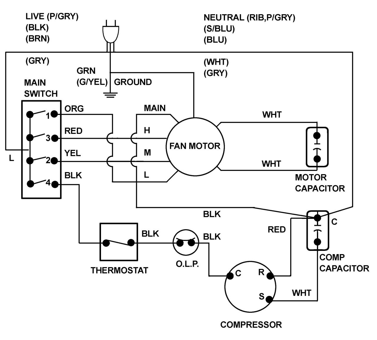
Samsung Fridge Compressor Wiring Diagram Refrigeration Diagrams Refrigerator C Electrical Circuit Diagram Refrigeration And Air Conditioning Electrical Diagram
Grundfos Pump Wiring Diagram Submersible Pump Submersible Well Pump Sump Pump

Goodman Air Handler Wiring Diagram Inspirational Thermostat Wiring Air Handler Goodman Heat Pump

3 Phase Motor Wiring Diagrams Non Stop Engineering Electrical Circuit Diagram Electrical Diagram Electrical Wiring Colours

Lewmar Windlass Wiring Diagram Upgrade Windlass Power Wiring Of Lewmar Windlass Wiring Diagram With Windlass Wiring Diagram For Windlas Diagram Power Wire Wire

Marine Power Inverter Wiring Diagram Trailer Wiring Diagram Diagram Wire

Unique Trane Heat Pump Thermostat Wiring Diagram Thermostat Wiring Electrical Diagram Trane Heat Pump

Frigidaire Wiring Diagram Newer Sc 1 St Appliance Aid Best In Frigidaire Wire Diagram

Walnut Innovations Automatic Water Level Controller Water Level Sensors For Single Ph Submersibles Operated Submersible Pump Submersible Well Pump Sump Pump

Fire Pump Wiring Diagram Electrical Diagram Electrical Circuit Diagram Motorcycle Wiring

60 Beautiful Motor Starter Wiring Diagram Electrical Circuit Diagram Circuit Diagram Electrical Wiring Diagram

Intertherm Thermostat Wiring Diagram Wiring Forums Diagram Diagram Chart Electrical Wiring Diagram