The circuit can be suitably modified to get pulses of sufficient length. A wiring diagram is a kind of schematic which makes use of abstract photographic symbols to reveal all the interconnections of components in a system.

Servo Motor Pinout Basic Electrical Wiring Electronics Projects Diy Motor
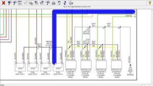
The schematic diagram of servo system for ac two phase induction motor is shown in the figure below.

Servo motor wiring diagram. Standard wiring examples ac servo system wiring 230 vac single phase or three phase 50 60 hz sign sign pulse pulse t ref gnd r s t l2 l1 c u v w fg a a b b z z 5v gnd cn2 mccb svc exx 0x0 encoder cable set mc servo drive pulse generator servo motor encoder vdd com com di 1 di 2 di 3 di 4 di 5 di 6 di 7 di 8 do 1 do 1 do 2 do. Signs that represent the components in the circuit as well as lines that represent. Servo motor wiring diagram what s wiring diagram.
It uses the cmos ic 7555 in the astable mode to generate pulses to drive the servo motor. Mg996r servo motor wiring diagram click the image to enlarge it the mg996r is a metal gear servo motor with a maximum stall torque of 11 kg cm. Servo motor preamplifier 3 circuit diagram tradeofic wiring darlington amplifier circuit diagram tradeofic we collect plenty of pictures about servo motor wiring diagram and finally we upload it on our website.
It shows the components of the circuit as streamlined forms and the power and signal connections in between the devices. Servo motor wiring diagram sample stepper motor wiring diagram elegant ponent series circuit diagrams. Servo drive schematic ac control wiring color code abb acs wiring diagram aac wiring diagram for s pickup ac power cord wire diagram ac fuse wiring diagram ac connector wiring diagrams ac cobra wiring harness ac blower motor wiring diagram fan a yamaha xs coil wiring ac compressor wiring aaon rooftop units wiring diagram a engine diagram ac disconnect box wiring diagram.
This is the simple basic design of servo motor controller with pulse generator. Again the controller must know the exact position of the rotor using encoder for precise speed and position control. Interfacing dc motor with pic microcontroller using l293d mikroc.
A wiring diagram is a simplified conventional pictorial depiction of an electric circuit. Couplings high ridigity disc o d 65mm clamping for servo. Like other rc servos the motor rotates from 0 to 180 degree based on the duty cycle of the pwm wave supplied to its signal pin.
You can t reverse the direction of a servo reversed servo by just swapping and wires. One thing to remember. The working principle of this servo motor is similar to the normal induction motor.
Many good image inspirations on our internet are the most effective image selection for servo motor wiring diagram. In futaba hitec and jr radio servos the servo and battery connections have the same polarity and signal wiring although the connectors are slightly different. Variety of servo motor wiring diagram.
Circuitry representations are composed of two points. A servo is a small device that has an output shaft. Working principle of ac servo motor.
Dc motor wiring diagram blurts.
How To Make A Simple Servo Motor Tester Circuit In 2020 Electronic Circuit Projects Circuit Circuit Projects

New Servo Wiring Diagram Arduino Diagram Diagramtemplate Diagramsample Circuito Electrico Arduino Circuitos

Mg90s Servo Wiring Diagram Metal Gear Rc Toys Motor

How Do You Build A Simple Circuit To Control A Servo Simple Circuit Electronics Circuit Electronics

Sweep Servo Motor With Arduino Nano All Arduino Arduino Projects Microcontrollers

Bluetooth Controlled Servo Motor Using Arduino Arduino Arduino Bluetooth Useful Arduino Projects

Servo Motor Circuit Diagram Electronic Engineering Electricity Motor

Servo Motor Control Using Potentiometer Arduino Uno Circuit Diagram In 2020 Arduino Circuit Diagram Analog Signal

Motiontek Ac Servo Motor Driver Cnc Kit Router Moinho Plasma Canada Eua Cnc Controller Diy Cnc Diy Cnc Router

Mearm Arduino Servo Motor Wire Schematic Arduino Servo Arduino Arduino Board

Arduino Servo Motor Control Using Joystick Circuit Projects Arduino Servo Arduino

Arduino And Pca9685 Circuit Schematic Arduino Motor Works Arduino Motor

Servo Motor Control Using Arduino Arduino Circuit Diagram Arduino Circuit

How Servo Motors Work How To Control Servos Using Arduino Howtomechatronics Arduino Arduino Projects Control

Arduino Tutorial Servo Motor Control With Potentiometer Arduino Arduino Projects Electronics Projects

New Servo Wiring Diagram Arduino Diagram Diagramtemplate Diagramsample

How To Control Servo Motor Using Joystick Full Program Code And Circuit Diagram Homemade Circuit Projects Circuit Projects Arduino Joystick

Mg996r Servo Motor Wiring Diagram Motor Rc Servo Metal Gear

Control A Servo Motor Without Programming Make Diy Electronics Cnc Software Electronics Circuit