It takes no active part in the operation of the fan. D Earth Connection To all unitsThis wire should be sleeved in a greenyellow earth sleeve.
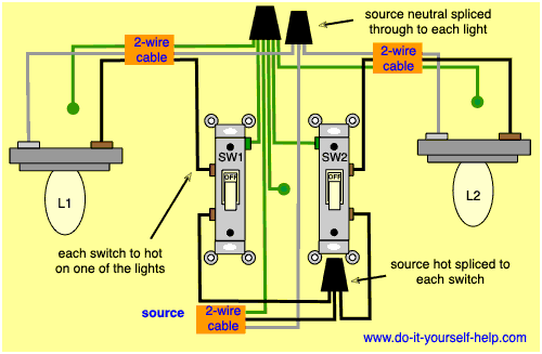
Wiring Diagram For Two Switches Controlling Two Lights Light Switch Wiring Home Electrical Wiring 3 Way Switch Wiring
Wiring Diagram for Gfci and Light Switch wiring diagram is a simplified up to standard pictorial representation of an electrical circuit.

Switched Live Wiring Diagram. WIRING DIAGRAM FOR MANROSE REMOTE. The electricity source and light are in between switches. Wiring an Extractor Fan With an Independent Switch not turned on by the light switch.
For detailed step-by-step instructions on completing this home. Switched lines and neutral connect to a 3-wire cable that travels to the lightfan outlet box in the ceilingThe fan control switch usually connects to the black wire and the light kit switch to the red wire of the 3-way cableIn this diagram the black wire of the ceiling fan is for the fan and the blue wire. Pin 2 is pulled HIGH using a 1 MΩ Resistor and Pin 6 is pulled LOW using a.
Here is a wiring diagram for a light switch three way light switch. Diagram showing wiring method for a timed fan. A standard 2-wire lighting circuit is shown in Figure 1.
The blue wire is known as the Switched Live and takes power to the light. The source is at SW1 and 2-wire cable runs from there to the fixtures. In the diagram below right a 2- wire NM cable that connects the light fixture to the switch carries 2 line wires one line and one switched line.
The source is at the outlet and a switch loop is added to a new switch. Timing adjustable from 1 Sec to 90 Mins. At the outlets each is wired using a pigtail splice to make the hot and neutral connections.
Light switch wiring diagram above shows electrical power entering the ceiling light electrical box and then continues to a wall switch using a 3 conductor cable. Hiring a qualified electrician will ensure that the installation is performed. A Switched Live Connection.
Wiring diagram for timer on live well in addition installation also boat livewell timer installation furthermore pump float switch wiring diagram along with keepalive bait tanks livewells furthermore aerator wiring diagram moreover attwood marine livewell. Switched boat aerator livewell timer 30 seconds x 3 minutes 10 amp model lws-t. These switches are utilised to operate a light from two distinct places.
The schematic shows that circuit is completed and. All wiring must be fixed securely and the cable to the fan should be a minimum For Timer Adjustment refer to the following diagrams. One light two switches wiring.
Dimmer Switch Wiring Diagram dimmer switch wiring diagram dimmer switch wiring diagram australia dimmer switch wiring diagram l1 l2 Every electric arrangement is made up of various unique components. The Switched Live would be placed in the NO terminal whilst. C Neutral Connection.
Switched Live is only live when the switch is on this is where it gets its name from. The permanent live wire is wired into the switch and the switched live into the switched live terminal. Neither hot the other three-way switch has been removed and its wires capped off.
L1 L2 Com Wiring Diagram wiring diagram is a simplified suitable pictorial representation of an electrical circuit. Before undertaking any electrical project it is imperative that you know precisely what it is youre doing and to keep in mind that electricity can kill. If the Switched live and Permanent Live was connected to the boiler before to do the switching of central heating on and off then our Boiler Switch will be able to do the same control.
Switches Fans from W down to 20W. 4 wire ceiling fan switch wiring diagram 4 Wire Ceiling Fan Switch Wiring Diagram New Wiring Diagram for Ceiling Fan Switch New Hunter. Each of the switches is.
Includes resitor for use with. This is an alternative way of wiring a lighting circuit. From the wall switch a 2 conductor cable is used to provide power to two electrical receptacle outlets.
The Boiler Switch gets installed into the Room Thermostat cables on the boiler wiring diagram. If the old fan was of the pull-switch type then the new live has to run from the light. The hot and neutral terminals on each fixture are spliced with a pigtail to the circuit wires which then continue on to the next light.
If not the arrangement wont work as it ought to be. Instead of taking the feed wire from the consumer unit to the ceiling rose it is taken to the switch. The neutrals are connected together using a terminal connector.
Light after switches power at the switch. They will be marked so you can tell which is. Switched White wires are shown in a different wiring diagram.
Wiring Diagram For House Lighting Circuit. The source is at SW1 and 2-wire cable runs from there to the fixtures. The bare wire is an earth wire and needs to be connected to an earth terminal.
The L1 is the switched live going out to the lightThey will be marked so you can tell which is which. In order to connect your new fan correctly you will need to run an extra live wire to the new fan. The wiring diagram above shows how.
Note – the switched live has a brown sleeve on it this highlights that the. Line diagram of a one way lighting circuit using in line method fig 1. Light before switches power at light fitting.
Adjustable Run On Time Start Delay. The permanent live wire is wired into the switch and the switched live into the switched live terminal. This diagram shows the wiring for multiple switched outlets on one switch.
The electricity source and light fixture are connected to the same switch. SWITCHED OUTLET WIRING DIAGRAMS Switched outlet wiring diagram depicts the electrical power from the circuit breaker panel entering the switched electrical receptacle outlet box where a two wire cable goes to the switch and another two wire cable feeds power to another outlet that is live at all times. Wiring Diagram for Multiple Switched Outlets.
The diagram shows the power entering into the circuit at the switch box location then sending one power line for the outlet which is hot all the time and a switched leg for the top half of the outlet being used for a table lamp or a floor fixture. The source for the circuit is at the switch and 2-wire cable runs to each receptacle outlet. With that said this electrical tutorial presents a guide to identifying the switched live wire on a lighting circuit and also explains how to rewire a ceiling rose.
B Permanent Live Connection. The connections for a switched outlet also known as a Half Hot Plug. Instead of taking the feed wire from the consumer unit to the ceiling rose it is taken to the switch.
The brown wire is Live also know as permanent live this brings the live supply to the switch. This diagram illustrates wiring for one switch to control 2 or more lights. Light switch wiring diagram shows electrical power entering the ceiling light electrical box and then continues to a wall switch using a 3 conductor cable.
Diagram 4 for mm 4. 96106472 Joystick Snow Plow Controller User Manual Manual Sno Way Snoway I Need Wiring Diagram For Switch At Pump Plowsite Sno Way 96105140 Wireless Snow Plow Control User Manual 7100737d Https Www Snoway Com Cm Pdfs Service 97101834d Pdf 981ba Fisher Plow Control Wiring Diagram Wiring Library Sno Way Plow Wiring Plowsite Sno Way. Multiple light switch wiring using NM cable.
In this diagram lights glow in pair means 2 lights glow.

2 Way Switch With Power Source Via Light Fixture How To Wire A Light Switch Home Electrical Wiring Light Switch Wiring Basic Electrical Wiring

Light Switch Wiring Diagram Multiple Lights Home Electrical Wiring Light Switch Wiring Installing A Light Switch

Installation Of Single Pole 3 Way 4 Way Switches Wiring Diagram Electrical Wiring Home Electrical Wiring Electrical Switch Wiring

60 Beautiful Motor Starter Wiring Diagram Electrical Circuit Diagram Circuit Diagram Electrical Wiring Diagram

Wiring Diagram Ac Generator Valid Modern Dc Wiring Gallery Circuit Diagram Electrical Circuit Diagram Diagram

Push Button Ignition Switch Wiring Diagram New Boat Wiring Kill Switch Electrical Wiring Diagram

Installing Turn Signals Motorcycle Wiring Electrical Diagram Electrical Wiring Diagram

Best Relay Wiring Diagram 5 Pin Bosch Electrical Circuit Diagram Circuit Diagram Electrical Diagram

On Off Switch Led Rocker Switch Wiring Diagrams Oznium Boat Wiring Automotive Electrical Automotive Repair

Daylight Running Lights Wiring Diagram Diagram Running Lights Daylight

Inspirational Wiring Diagram For Rock Lights Diagrams Digramssample Diagramimages Wiringdiagramsample Wiringdia Bar Lighting 12v Led Lights Led Light Bars

Ceiling Fan Wiring Diagram 1 Ceiling Fan Wiring Electrical Wiring Home Electrical Wiring

Light Switch Wiring Diagram Basic Electrical Wiring Light Switch Wiring House Wiring

Wire Harness Wiring Cdi Assembly For 50 70 90 110cc 125cc Atv Quad Coolster Go Kart Wish In 2022 Motorcycle Wiring 90cc Atv Chinese Scooters

Wiring Diagram 3 Way Switch With 2 Lights Wiring Diagram Light Switch Wiring 3 Way Switch Wiring Home Electrical Wiring

Alternate 4 Way Switch Wiring Diagram Light Switch Wiring 4 Way Light Switch 3 Way Switch Wiring
Best Bosch Relay Wiring Diagram 5 Pole Electrical Outlet Symbol 2018 Electrical Circuit Diagram Light Switch Wiring Electrical Wiring Diagram

Lewmar Windlass Wiring Diagram Upgrade Windlass Power Wiring Of Lewmar Windlass Wiring Diagram With Windlass Wiring Diagram For Windlas Diagram Power Wire Wire

Wiring Diagram To Add A New Outlet Off A Light Fixture Home Electrical Wiring Electrical Wiring House Wiring