This wiring diagram illustrates adding wiring for a light switch to control an existing wall outlet. It stands for the electric elements of the circuit as little detailed forms and offers the needed connection and also power connections between the different devices.
Wiring Diagrams To Add A Receptacle Outlet 3 Way Switch Wiring Electrical Plug Wiring Electrical Wiring
A wiring diagram and a circuit diagram are shown below.

Wiring Diagram For Light Switch And Outlet. Wiring Diagram comes with several easy to stick to Wiring Diagram Instructions. The first component is emblem that indicate electric element from the circuit. Wiring A Light Switch And Outlet Together Diagram Every electric structure is composed of various unique components.
The connections for a switched outlet also known as a Half Hot Plug. The source is at the outlet and a switch loop is added to a new switch. Multiple receptacle outlets can be connected with lighting outlets as depicted in the above light switch wiring diagram.
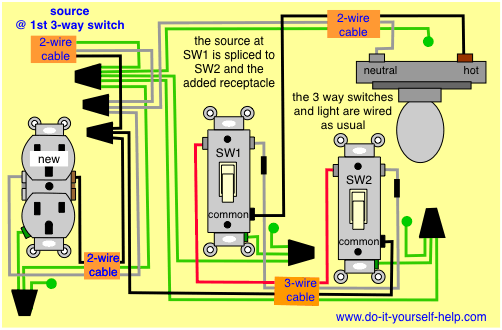
The source is at SW1 and 2-wire cable runs from there to the fixtures. Notice that these outlets have the tab removed from the hot side or Brass side of the outlet which allows the top half of the plug to be controlled only from the switch. At the outlets each is wired using a pigtail splice to make the hot and neutral connections.
Socket Outlet Wiring Diagrams. Wiring diagram for light switch and outlet in same box. In the diagram below right a 2-wire NM cable that connects the light fixture to the switch carries 2 line wires one line and one switched line.
These guidelines will likely be easy to comprehend and implement. Components of Wiring A Light Switch And Outlet Together Diagram and Some Tips. Switched outlet wiring diagram depicts the electrical power from the circuit breaker panel entering the switched electrical receptacle outlet box where a two wire cable goes to the switch and another two wire cable feeds power to another outlet that is live at all times.
Wiring A Switch And Outlet The Safe And Easy Way Family Handyman Wiring A Light Switch And Outlet Together Diagram. Wrapping the wire clockwise when wiring a light switch ensures that the loop on the end of the wire will tend to close when the screw is tightened. This diagram illustrates wiring a gfci receptacle and light switch in the same outlet box a common arrangement in a bathroom with limited space.
4 Way Switch Wiring Diagram GFCI Outlet Wiring Diagram. The wiring diagram above shows how switched outlets are often wired. This diagram illustrates wiring for one switch to control 2 or more lights.
Its supposed to help all the typical consumer in creating a correct system. Light switch wiring diagram shows electrical power entering the ceiling light electrical box and then continues to a wall switch using a 3 conductor cable. The hot and neutral terminals on each fixture are spliced with a pigtail to the.
The first element is symbol that indicate electric element in the circuit. Wiring Diagram For Light Switch And Outlet. For wiring in series the terminal screws are the means for passing voltage from one receptacle to another.
Its supposed to help each of the common user in developing a correct system. A two way light switch is a simple single pole changeover switch with three terminals. The break away fin tab is intact therefore line hot is connected to the only one brass terminal on line side.
There are just two things that will be present in any Wiring A Light Switch And Outlet Together Diagram. Wiring Diagram For Light Switch And Outlet A wiring diagram is an common photographic depiction of a intricate electric circuit which is made by connecting one part to an additional one. Switch Box Wiring At the switch box the white neutral wires are spliced together and the ground wires are spliced and a pigtail wire is added and attached to the green ground.
A switch loop single-pole switches light dimmer and a few choices for wiring a outlet switch combo device. Switch and outlet combo electrical 101 leviton 15 amp tamper resistant combination white r62 t5225 0ws the decora t5625 wiring a. SWITCHED OUTLET WIRING DIAGRAMS Switched outlet wiring diagram depicts the electrical power from the circuit breaker panel entering the switched electrical receptacle outlet box where a two wire cable goes to the switch and another two wire.
Dec 06 2020 according to earlier the lines in a wiring a light switch and outlet together diagram represents wires. A switch loop single pole switches light dimmer and a few choices for wiring a outlet switch combo device. Multiple Light Wiring Diagram.
Wiring an Outlet to a Switch Loop. The hot source wire is removed from the receptacle and. With this wiring project the outlet will provide the power source for the light fixtures which are controlled by the light switch so the wire from the outlet leads to the switch location and then to the light fixture.
The above light switch wiring diagram depicts the power from the circuit breaker panel going to an electrical receptacle outlet and then continues to the next outlet and then to a single pole wall switch and then to another outlet. Wiring diagram for light switch and outlet combo. How to wire a light switch and outlet wiring diagrams for switched wall on the 2 way with garbage electrical outlets switches house connection in same box two lights add new half hot three 3 4 1 wired rewire that controls an gfci receptacle hs200 diagram do it car sonoff.
Nancy October 21 2017 at 440 AM. In this diagram a 2-wire NM cable supplies line from the electrical panel to the switch outlet boxThe black wire line connects to a switch terminal and the black wire of a 3-wire NM cable that travels to the split receptacle boxThe white wire neutral connects to the white wire of the 3-wire NMA 3-wire NM cable connects from the switch box to. A circuit is generally composed by various components.
There are just two things that will be found in any Light Switch To Outlet Wiring Diagram. Wiring Diagrams To Add A New Receptacle Outlet Do It Yourself Help Com. The other thing that you will see a circuit diagram could be traces.
Light switch wiring diagram shows electrical power entering the ceiling light electrical box and then continues to a wall switch using a 3 conductor cable. Wiring Diagram will come with a number of easy to follow Wiring Diagram Directions. In this simple wiring diagram the combo switch outlet is connected to the 120V AC supply through CB.
Wiring A Switch And Outlet The Safe And Easy Way Family Handyman Wiring Lights And Outlets On Same Circuit Diagram. Wiring a Light bulb with Combo Switch and Outlet. A circuit is usually composed by many components.
2 way switches 3 way switches and 4 way switches. These directions will likely be easy to grasp and apply. The neutral is connected to the neutral silver terminal.
In the wiring diagram above a hot and a neutral enter the single pole switch box. Usually the switches only do ON or OFF the device that is connected with it. Universal Brake Light Switch Wiring Diagram.
The diagram shows the power entering into the circuit at the switch box location then sending one power line for the outlet which is hot all the time and a switched leg for the top half of the outlet being used for a table lamp or a floor fixture. The light switch is an electrical component used to control and operate the lights bulbs the equipment connected with it and any electrical outlet connected with itSwitches are of different types and are used for different purposes.

Combination Switch Receptacle Wiring Diagram Wiring Diagram Combo Switch Electrical Switch Wiring Light Switch Wiring Wire Switch

Wiring Diagram To Add A New Outlet Off A Light Fixture Home Electrical Wiring Electrical Wiring House Wiring

Gfci Outlet Wiring Diagram Electrical Wiring Diagram Outlet Wiring Home Electrical Wiring

Wiring A 2 Way Switch Home Electrical Wiring Diy Electrical Outlet Wiring

Wiring A Switch And Outlet In Same Box In The Middle Of The Circuit Light Switch Wiring Home Electrical Wiring Basic Electrical Wiring

Diagram To Add A New Outlet Off A 3 Way Light Switch Electrical Wiring 3 Way Switch Wiring Electrical Wiring Diagram

Electrical Outlet 2 Way Switch Wiring Diagram How To Wire Light With Receptacl Light Switch Wiring Outlet Wiring Home Electrical Wiring

Wiring Diagram For Two Switches In One Box With 2 Sources Light Switch Wiring Double Light Switch Home Electrical Wiring

Wiring Diagram For A Gfci Outlet And Light Switch In The Same Box Outlet Wiring Electrical Wiring Light Switch Wiring

Wiring Diagrams To Add A Receptacle Outlet Electrical Wiring Home Electrical Wiring Diy Electrical

Wiring A Outlet Switch Combo With Two Electrical Sources Light Switch Wiring Wire Switch Home Electrical Wiring

Split Combo Device With Second Receptacle Wiring A Plug Home Electrical Wiring Light Switch Wiring

Wiring Diagrams To Add A Receptacle Outlet Home Electrical Wiring Electrical Wiring Diagram Light Switch Wiring

2 Way Switch With Electrical Outlet Wiring Diagram How To Wire Outlet With Light Switch Light Switch Wiring Outlet Wiring Home Electrical Wiring

Wiring Diagram Outlet To Switch To Light 3 Way Switch Wiring Light Switch Wiring Wire Switch
Wiring Switched Split Outlet With Source And Receptacle First Complies With Nec 2011 Outlet Wiring Light Switch Wiring Electrical Wiring Diagram

Wiring A Switched Outlet In One Box Home Electrical Wiring Basic Electrical Wiring Electrical Wiring Diagram

Image Result For Electrical Outlet Wiring With Switch Wire Switch Outlet Wiring House Wiring

Diagram For Two Switches Controlling One Split Outlet Light Switch Wiring Wire Switch Outlet Wiring