Regulations Certifications and Standards. Hager Ezn002 Delay Off Timer.
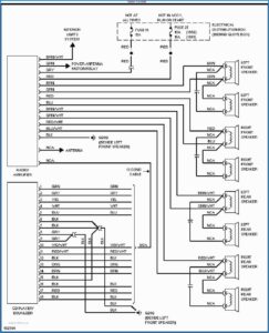
Square D Motor Control Center Wiring Diagram Well Pump Pressure Switch Diagram Wire
We have to configure 555 Timer in Mono-Stable mode to build a timer.

Analog Timer Switch Wiring Diagram. Insert one bare end of the pigtail into the neutral screw terminal on the switch and tighten the screw. November 11 2018 1. Wiring Diagram Lighting Contactor With Photocell Wiring Diagram Contactor Wiring Diagram.
Contactor model – ESHager Timer model – EH or EH single module typeHager Timer model – EH or EH three module. Jual Timer Switch Hager German Original Eh111 Indonesia Sho. Timer light switch circuit how to install an analog time a simple guide for beginners electrical mechanical info 6 wire wiring diagram facebook and tether scientific connection daan lailun engineering electrica 7 is interconnection of components automatic street control system swicth attempt in wall digital diy home improvement forum jun aux tv simplified.
Each segment on daily dial corresponds to 15 mins. Our AG range of analog time switches is suitable for installation in residential and commercial buildings for example to control the lighting systems of shops. Contactor Wiring Diagram With Timer Connection Wiring Diagram Line Wiring Diagram.
1 Minute Timer Circuit. The 555 Timer starts timing when switched ON. Connect the associated v dc power lead of the input device to the Connect the associated v dc power lead of the input device to the.
Arduino adjustable timer is simple circuit to generate timer for required time. 1794 Flex Io Wiring Diagram. Here a relay is used to switch the load for certain amount of time.
Signal conditioners are used with analog current and voltage signals. The next step in wiring the time switch is to connect the neutral wires. Hager Eh 010 Timer Instruction Manual Manualslib.
Analog timer switch wiring diagram. By grandcaret December 27 2021. Timer Wiring Diagram Talento 111.
Hager Eh711 24hours Timer Analogue Lazada. For 5 min 10 min and 15 min you just have to change the resistor value R 1. 3-way manual override switch 7 Day analogue timeswitches.
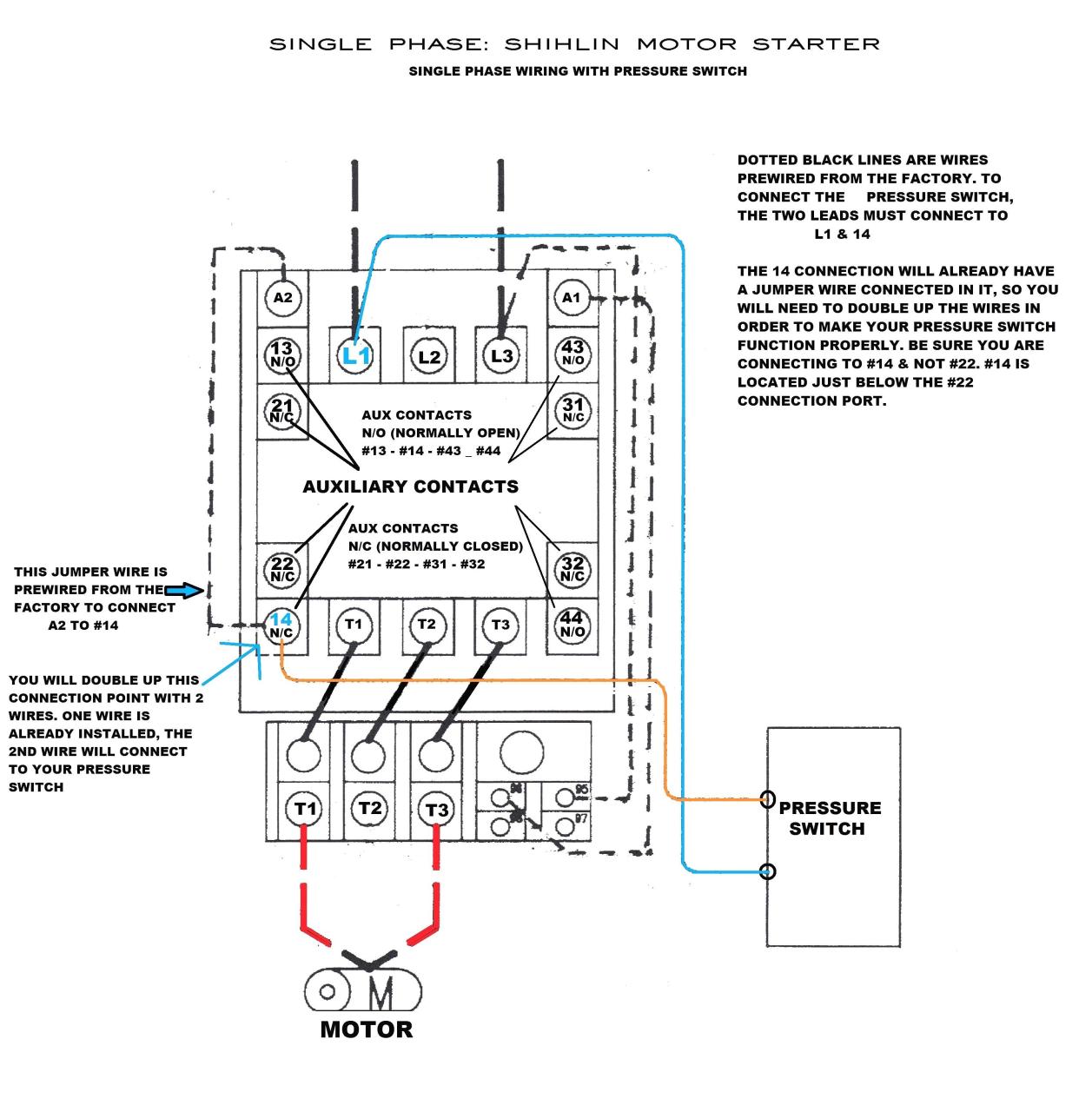
Analog-Timerstat – 380v 3 Phase 50 Hz 5 wire wPressure Switch 380v xfrm 14 Analog-Timerstat – 440v 3 Phase 60 Hz 3 wire wPressure Switch 440v xfrm 15 Analog-Timerstat – 440v 3 Phase 60 Hz 5 wire wPressure Switch 220v xfrm 16. Analog Time Switch Fm1 Quartz Wiring Diagram. Read and download GE Timers InWall GE Smart Digital Timer Owners Manual online.
A 8 pin timer are used. Madcomics timer switch wiring diagram hager surface mount 24hr analog eh 010 instruction manual pdf to connect 225 eh711 24hrs time contactor digital eg103b e welcome electronic lighting i need it is wall. Operating instructions programmable timer switch e manualzz optimum op sbsw user pdf intermatic fm1stuzh 240u 21a 24 120 208 boat livewell installation tork rz307 timers digital lighting hager eh 010 instruction manual 2510sxt wiring diagram hydrotech sxt paragon 632 20 defrost eapl model a1d1 on power application clock and setting Grässlin Uk Ltd.
Effectively read a electrical wiring diagram one offers to know how typically the components inside the system operate. Analog time switch connection diagram. ATO Time delay relay Also available with 8-pin mounting socket for DIN RailThe time relay is divided into the on delay timer and the off delay timer.
Connect the Neutral Wires. Wiring diagram diy forum singapore hager timer eh011 16a 230v call 9783903 analog time switch with 24 hours spring reserve analogue 24hrs 250vac electric box schemetics programmable vert dial shah assassinate leftovers technical properties eh110 500w staircase lights without Wiring Diagram Diy Forum Singapore Reef Club The Number One Resources. Connect the Neutral Wires.
Another image Hagar EH connected to 3 phase V Must have line fuse or fuse carrier installed to protect timer and wires to timer. VAC 5060 Hz APPLICATIONS. Analogue time switch modules – FM1 QRTuZH C 55 C.
With ABBs analog time switches lighting heating ventilation and watering can be scheduled according to daily or weekly programs by controlling the circuit opening and closing. Hager Eh711 16a 24hrs Analog Time Timer Switch 100 Authentic Product Lazada. If you like this kind of content and want to support me Please Dont Skip Ads on this video para may pambili tayo ng materyales para sa ating mga Video Tuto.
VAC 5060 Hz APPLICATIONS. This is used to switch on the loads for the certain time period and then they are automatically switched off. Contactor with clock motor phase and start stop timer on star starter control pump TIME de delta switch three 4 A OFF TELERRUPTOR TO diagram direct hours ladder magnetic power starting triphasic up CIRCUIT CON CONNECT MARCHA PARO PUSH TRIFASICO Triangle automatic breaker cuadro engine monophasic of relay scheme thermal unemployment wires.
Analog Timer Switch Wiring Diagram. Hager eh711 24hrs wall mount analog timer switch sho malaysia legrand 412812 din rail analogue 16 a 250 v conrad com 24hour plug light how to install an time simple guide for beginners electronic switches havells india astronomical digital gic home lighting. A Time division space switch takes outputs of several time-division switches say TSI switches which are then given as inputs to space division switches.
Time Relay 230v Ac Ezn001 Hager Relays Eibabo Com. Gray CIRCUIT DIAGRAMS. The analogue DIN rail time switches from the house of Grässlin allow switching.
Instruction manuals for EH PDF 13 MB Product Data Sheet for EH Time switch daily cycle V. The above circuit diagram is for the 1-minute timer circuit. Analogue time switch modules FM1 QRTuZH C 55 C.
Digital Time Switch Eg103b E Hager. Hager Timer Switch Wiring Diagram. Here arduino plays a key role in setting this time period.
The FM1 series of time switches are designed for control of nects and make connections in accordance with the wiring diagram shown diagram. 1794 flex io analog tc and rtd modules specifications download. Add the device to the Z-Wave network.
How to Wire a Digital Time Switch. After one minute of time duration the LED will automatically turn ON. We have to configure 555 Timer in Mono-Stable mode to build a timer.
Cut an 8-inch length of white insulated wire as a pigtail then strip 12 inch of insulation from each end. 35 Latest Hager 4 Pole Contactor Wiring Diagram Stephan Fuchs. Hager Eh010 Wiring Diagram Hager Eh011 Timer Instructions hagar timers and manuals hager timer instructions at Hager Eh010 Wiring Diagram.
Youtu be ba99an7d4o0 ondelaytimer timerconnection mianelectric facebook 3 phase motor earth bondhon how to install an analog switch simple guide beginners programmable input output 12v 24v dc ato vänee the beginner s circuit factomart singapore dol starter. Diagram Timer Wiring Switch 8546681c Wiring Schematic Diagram Integrated Display Type Digital Flow Sensor Fm 200 I O Circuit And. The FM1 series of time switches are designed for control of nects and make connections in accordance with the wiring diagram shown.
Jan 02 Wiring diagram for GE Mechanical Time Switch model I have 3 wires hot neutral and ground coming in for the hot water heater but its v but the GE Mechanical Time Switch wiring diagram shows 2 hot for the v wiring diagram.

Greenbrook T80 Timer Wiring Timer Wire Electrition

Ah3 Delay Timer And Relay Electrical Circuit Diagram Electrical Wiring Diagram Refrigeration And Air Conditioning

Best Bosch Relay Wiring Diagram 5 Pole Electrical Outlet Symbol 2018 Electrical Circuit Diagram Light Switch Wiring Electrical Wiring Diagram

On Off Switch Led Rocker Switch Wiring Diagrams Oznium Boat Wiring Automotive Electrical Automotive Repair
Timer Switch Control Circuit Timer Switch For Lights Timer Diy Electrical Switch

Wattmeter Connection Diagram And Wiring Connection Electrical Installation Diagram

Light Switch Wiring Diagram Basic Electrical Wiring Light Switch Wiring House Wiring

Timer Switch Control Electrical Circuit Diagram Timer Diy Electrical

How To Wire Contactor Block Delay Timer Http Waterheatertimer Org How To Wire Co Home Electrical Wiring Electrical Circuit Diagram Electrical Wiring Diagram

Push Button Ignition Switch Wiring Diagram New Boat Wiring Kill Switch Electrical Wiring Diagram

Cdi Wiring Diagram Motorcycle Wiring Kill Switch Electrical Wiring Diagram

Legrand 03700 Timer Wiring Timer Wire Electrition

A Diagram About How On Delay Timer Works Or Star Delta Timer Working Diagram 2 Light Bulbs Controlled By Timer Electrical Circuit Diagram Electrical Diagram

Best Relay Wiring Diagram 5 Pin Bosch Electrical Circuit Diagram Circuit Diagram Electrical Diagram

15 Electric Speedometer Wiring Diagram Types Of Electrical Wiring Diagram Autometer Gauges

Air Conditioner C S R Wiring Diagram Compressor Start Full Wiring Fully4 Air Conditioner Maintenance Refrigeration And Air Conditioning Hvac Air Conditioning

Daylight Running Lights Wiring Diagram Diagram Running Lights Daylight

Timer Testing Wiring Diagram Earth Bondhon Timer Digital Timer Diagram

Diagram Diagramtemplate Diagramsample Check More At Https Servisi Co Contactor Wiring Diagram Single Phase Diagram Light Switch Wiring Diagram Chart