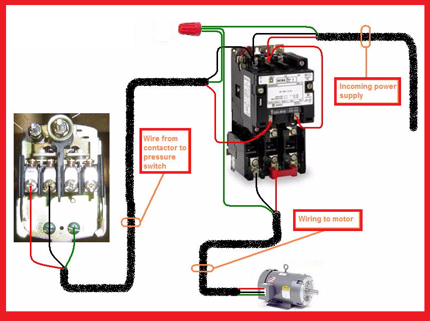
The above diagram is a complete method of single phase motor wiring with circuit breaker and contactor. The electricity that passes through the contacts of the starter through the overload relay and out to the motor is called the power.
Single Phase Motor Contactor Wiring Diagrams Png 848 632 Electrical Wiring House Wiring Electricity
Phase 2 l1 l2 l3 ground when used.

Motor starter wiring diagram. If you are not sure of how to make the connections on your equipment hire an electrician. In the above one phase motor wiring i first connect a 2 pole circuit breaker and after that i connect the supply to motor starter and then i do cont actor coil wiring with normally close push button switch and normally open push button switch and in last i do connection between capacitor. Wiring diagrams sometimes called main or construction diagrams show the actual connection points for the wires to the components and terminals of the controller.
Please refer to the manufacturer s literature if in doubt. Wiring diagrams show the connections to the controller. Square d motor starters wiring diagram sq d motor starter wiring diagram square d 3 phase motor starter wiring diagram square d 8536 motor starter wiring diagram every electric structure is composed of various distinct pieces.
A motor starter is a combination of devices used to start run and stop an ac induction motor based on commands from an operator or a controller. Star delta y δ 3 phase motor starting method by automatic star delta starter with timer. Wiring diagrams do not show the operating mechanism since it is not electrically controlled.
There are two circuits to a starter the power circuit and the control circuit. Each part should be placed and linked to different parts in specific way. They are used in applications which do not require undervoltage protection.
If not the structure won t work as it ought to be. Refer to the motor manufacturer s data on the motor for wiring diagrams on standard frame ex e ex d etc. In north america an induction motor will typically operate at 230v or 460v 3 phase 60 hz and has a control voltage of 115 vac or 24 vdc.
Three phase motor power control wiring diagrams three phase motor connection schematic power and control wiring installation diagrams. Inst maint wiring qxd 5 03 2008 10 02 am page 6. Wiring diagrams bulletin 609 manual starters are operated by start stop push buttons mounted on the front of the starter.
Basic wiring for motor control technical data. These diagrams are current at the time of publication check the wiring diagram supplied with the motor. Typical controller markings typical elementary diagram iec typical controller markings typical elementary diagram table 4 control and power connections for across the line starters 600 v or less from nema standard ics 2 321a 60 1 phase 2 phase 4 wire 3 phase line markings l1 l2 l1 l3.
Basic wiring for motor contol circuitry of a starter the two circuits of a motor starter are the power and con trol circuits. Your motor starter may use wiring which is internal to the starter wiring which is different than the diagrams etc. Phase 1 l2 l4.

Starting Capacitor Wiring Diagram With Single Phase Motor Start At Electrical Circuit Diagram Circuit Diagram Capacitors

Single Phase Starter Connections Circuit Diagram Diagram Single

Star Delta Motor Connection Diagram Elec Eng World Electrical Circuit Diagram Electrical Wiring Diagram Basic Electrical Wiring
Single Phase Submersible Pump Starter Wiring Diagram Gooddy Org Best Of Submersible Pump Submersible Submersible Well Pump

60 Beautiful Motor Starter Wiring Diagram In 2020 Electrical Circuit Diagram Circuit Diagram Auto Transformer

Contactor Wiring Diagram With Schematic And Diagrams Vaerksted Pinterest Knapper

Wiring Diagram For Motor Starter 3 Phase Controller Failure Relay Electrical Pleasing Three And Contactor Teknik Listrik Rangkaian Elektronik Listrik

Starting System Diagram Starter Motor Motorcycle Wiring Automotive Repair

Direct On Line Dol Motor Starter Basic Electrical Wiring Electrical Circuit Diagram Circuit Diagram

Direct On Line Starter Wiring Diagram Directions Electrical Diagram Dol

Pin By Gemnest Eco Warrior Eco Warrio On Tools In 2020 Line Diagram Electrical Diagram Electricity

Direct Online Starter Dol Starter Wiring Diagram Diagram Electronic Engineering Motor

Electrical Contactor Wiring Diagram Dat Wiring Diagrams In 2020 Electrical Circuit Diagram Circuit Diagram Electrical Projects

35 Lovely Square D Manual Motor Starter Wiring Diagram In 2020 Diagram Circuit Diagram Wire

Mem Contactor Wiring Diagram New Mem Dol Starter Wiring Diagram Inspirationa A Save Motor Of Or Diagram Timer Wire

Forward And Reverse Motor Starter Wiring Diagram Elec Eng World Electrical Circuit Diagram Circuit Diagram Electrical Diagram

Cutler Hammer Motor Starter Wiring Diagram In Allen Bradley Control Diagrams On Contactor Symbol 715 Gif Dry Type Transformer Diagram Electrical Wiring Diagram

Dol Starter Panel Wiring Diagram Save Start Stop And Motor Electrical Circuit Diagram Circuit Diagram Electric Circuit

Direct On Line Dol Wiring Diagram For 3 Phase With 110 230vac Control Circuit Electrical Circuit Diagram Circuit Diagram Electrical Wiring Diagram