Ge brands include general electric hotpoint rca and others. The 555 Timer starts timing when switched ON.
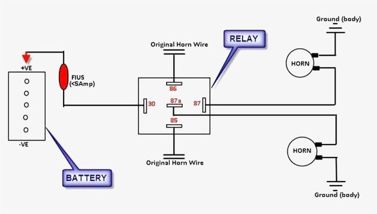
Horn Wiring Car Horn Electricity Horns
No pressure build up 1.

Timer Switch Wiring Diagram. L T Gic J648b1 Timer Switch For Rs 1050 Piece True Sense Technologies Id 21813424033. Applying power starts the timer. Immersion heater timer switch.
Intermatic Fm1stuzh 240u 21a 24 120 208 240v Analog Or Mechanical Timer Switch Installation Manual Manualzz. Each component should be placed and linked to other parts in particular manner. On delay timer circuit diagram wiring diagram contactor with push button circuit diagram of delay timer on off power off delay timer circuit diagram 2 way lighting circuit triggering transformer push button fan switch light activated switch circuit diagram wd081 text.
Consult your timers wiring diagram to ensure which wire is the hot lead from the switch. 9 Automatic Wiring Diagram Of Washing Machine Timer Samples Bacamajalah Washing Machine Motor Whirlpool Washing Machine Washing Machine And Dryer. A wiring diagram is a streamlined traditional photographic depiction of an electrical circuit.
The circuit works off 12 volt dc supply. That is going to cause the 3-way switch to provide power to both the black and red travelers all the time. Timer And Contactor Wiring Diagram Wiring Diagram Line Wiring Diagram.
Insert one bare end of the pigtail into the neutral screw terminal on the switch and tighten the screw. The above circuit diagram is for the 1-minute timer circuit. In event that you do not have this white neutral wire you can connect ground wire to terminal 2.
In the wiring diagram above it shows white neutral wire running to Tork timer terminal 2. Watch me wire the timer switch set the timer on and off wire multiple lights and discuss how timer switch work. Wiring Diagram for P900 Displays with AT411 Timerspdf.
The SENSOR WORX interval timer switch provides an automatic lighting control solution that is intuitive to operate. Then connect the switched wire typically a blue wire to the black wire leading to the device. We have to configure 555 Timer in Mono-Stable mode to build a timer.
TagalogFor more information watch the fu. Cut an 8-inch length of white insulated wire as a pigtail then strip 12 inch of insulation from each end. As described above the wiring will require four wires for the connections to the time switch.
How to Wire a Timer Switch for Lighting. I have two light switches in a box and Im wanting to replace one with a timer. 3-Way Switch Wiring Diagram NM Cable A very common type of 3-way electrical diagram is when the power supply wire moves from one switch to the second switch and finally terminates at the fixture.
November 27 2021 on Staircase Timer Switch Wiring Diagram. The 555 Timer starts timing when switched ON. Intermatic T86A Transformer for sprinkler timer Or install 20 amp line fuse between incoming Hot wire and timer and this will allow timer to control any.
Wiring a contactor on timer doityourself com community forums how to use low cur switch control high load knowledge sichuan holso science and technology co ltd single phase motor. Leviton Vpt24 1pz Viziarf 24 Hour Programmable Timer 120vac Installation Manual Manualzz. Single Pole One location or 3.
Hager eh711 24hrs wall mount analog legrand 412812 din rail timer 24hour plug light how to install an time switch a electronic switches havells india astronomical digital mechanical automatic street control system circuit eh 711 made in china. This terminal may be marked NEUTRAL or it may be indicated by a silver-colored screw. It reveals the components of the circuit as simplified forms and also the power and signal links in between the gadgets.
Operating instructions programmable timer switch e manualzz optimum op sbsw user pdf intermatic fm1stuzh 240u 21a 24 120 208 boat livewell installation tork rz307 timers digital lighting hager eh 010 instruction manual 2510sxt wiring diagram hydrotech sxt paragon 632 20 defrost eapl model a1d1 on power application clock and setting Grässlin Uk Ltd. 1 Minute Timer Circuit. Wiring Diagram Line We are make source the schematics wiring diagrams and technical photos.
Timer light switch circuit how to install an analog time a simple guide for beginners electrical mechanical info 6 wire wiring diagram facebook and tether scientific connection daan lailun engineering electrica 7 is interconnection of components automatic street control system swicth attempt in wall digital diy home improvement forum jun aux tv simplified. RPC SprinklerIrrigation Time Switch with Day Skipper These irrigation timers are designed to permit one to 44 ON operations every 24 hours. Ron the digital time switch that you have requires a separate neutral wire.
Ah3 Delay Timer Wiring With Push Button Electrical Circuit Diagram Timer Basic Electronic Circuits. It includes instructions and diagrams for different varieties of wiring strategies as well as other items like lights windows and so on. Intermatic Sprinkler Timer Wiring Diagram.
The wiring diagram is in their manual. Two Way Light Switch Diagram Or Staircase Lighting Wiring Diagram Home Electrical Wiring Wire Lights Electrical Wiring. If we observe the above circuit the.
Ts18 Timer Wiring Diagram. Contactor Wiring Diagram With Timer New 240 Volt Hvac Wiring Wiring Diagram Write House Wiring Basics House Wiring Home Electrical Wiring. 2 Way Switch Wiring Diagram Light Wiring Electrical Switch Wiring Diagram Wiring Diagram consists of several detailed illustrations that present the link of assorted things.
After one minute of time duration the LED will automatically turn ON. Exhaust fan wiring diagram timer switch gz 7051 bathroom light schematic with and heater motor a extractor an isolator diagrams for ceiling kit do it yourself xg 4619 electrical on in vent double tosmun aw 6644 wire guide to installing fans exhaust fan wiring diagram timer switch gz 7051 wiring diagram bathroom light schematic wiring exhaust. Diagram Outdoor Light Timer Wiring Diagram Full Version Hd Quality Wiring Diagram Carbeltdiagrams Andreapendibene It.
The Digital Timer has 5 wires Red Black White Blue and Ground green. Your wiring configuration will not work with this timer unless there is a neutral wire in the switch box. Timer Switch Control Circuit Timer Switch For Lights Timer Diy Electrical Circuit.
For 5 min 10 min and 15 min you just have to change the resistor value R 1. Wiring Leviton Timer To Bath Fan And Switch To Light Home Improvement Stack Exchange. Bring this white neutral wire from any nearby volt outlet.
Wiring diagram diy forum singapore hager timer eh011 16a 230v call 9783903 analog time switch with 24 hours spring reserve analogue 24hrs 250vac electric box schemetics programmable vert dial shah assassinate leftovers technical properties eh110 500w staircase lights without Wiring Diagram Diy Forum Singapore Reef Club The Number One Resources.

Legrand 03700 Timer Wiring Timer Wire Electrition

Square D Motor Control Center Wiring Diagram Well Pump Pressure Switch Diagram Wire

On Off Switch Led Rocker Switch Wiring Diagrams Oznium Boat Wiring Automotive Electrical Automotive Repair

A Diagram About How On Delay Timer Works Or Star Delta Timer Working Diagram 2 Light Bulbs Controlled By Timer Electrical Circuit Diagram Electrical Diagram

Cdi Wiring Diagram Motorcycle Wiring Kill Switch Electrical Wiring Diagram

Push Button Ignition Switch Wiring Diagram New Boat Wiring Kill Switch Electrical Wiring Diagram

Greenbrook T80 Timer Wiring Timer Wire Electrition

Starter Wiring Help Electrical Circuit Diagram Electricity Wire
5 Pin Relay Wiring Diagram Electrical Circuit Diagram Circuit Diagram Electrical Diagram

Lovely Wiring Diagram Alternator Diagrams Digramssample Diagramimages Wiringdiagramsample Wiringdiagr Light Switch Wiring Porch Lighting Porch Light Timer

Timer Switch Control Electrical Circuit Diagram Timer Diy Electrical

Unique Wiring Diagram For Chinese 110cc Atv Wiring Diagram Chinese Atv Wiring Diagrams Roketa 11 Motorcycle Wiring Electrical Diagram Electrical Wiring Diagram

Best Bosch Relay Wiring Diagram 5 Pole Electrical Outlet Symbol 2018 Electrical Circuit Diagram Light Switch Wiring Electrical Wiring Diagram

How To Wire Off Delay Timer Timer Electrical Wiring Colours Electrical Circuit Diagram

Diagram Diagramtemplate Diagramsample Check More At Https Servisi Co Contactor Wiring Diagram Single Phase Diagram Light Switch Wiring Diagram Chart

Lewmar Windlass Wiring Diagram Upgrade Windlass Power Wiring Of Lewmar Windlass Wiring Diagram With Windlass Wiring Diagram For Windlas Diagram Power Wire Wire

Installing Turn Signals Motorcycle Wiring Electrical Diagram Electrical Wiring Diagram

Timer Switch Control Circuit Timer Switch For Lights Timer Diy Electrical Switch

This Post Is About The Staircase Timer Wiring Diagram In The Diagram I Use The On Delay Timer Finder 8 Pin Relay Re Timer Electrical Circuit Diagram Diagram