Its designed to replace all the Honeywell part s listed below. Direct Coupled Actuators – Spring Return Models ML ML ML and ML Typical 24 Vac wiring.
Fan Limit Switch Q A 5 Furnace Fan Limit Control Troubleshooting
Mount the ST9120U Electronic Fan Timer in the appliance wiring compartment using the two 8 12-in.
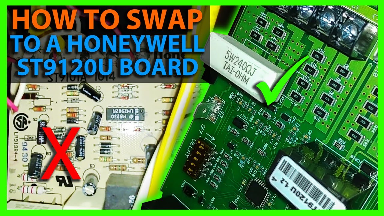
St9120u Wiring Diagram. When i use this same board in the field all i have to go off of his the manual and the furnace wiring diagram. The ST wiring adapter. Wiring CAUTION Explosion or fire hazard.
OEM York Coleman Furnace Gas Valve Wiring Harness 025-31810-000 S1-02531810000. It really takes some wiring knowledge to convert a universal board sometimes. Mount the ST9120U Electronic Fan Timer in the appliance wiring compartment using the four provided No.
It is approx 22 between the housings. – i wish that they had wire for wire instruction for each of the models listed that they replace but those do not exist. These guidelines will probably be easy to understand and use.
Turn off power to appliance. Take the blue wire on the ST9101 wiring adapter and connect to the D1 quick connect terminal on the ST9120U 7. How to Read Wiring Diagram.
Wiring make sure that all wiring complies with local codes and. Replaces all existing ST9101 ST9120 ST9141 and ST9160 fan timers and ST9150A 1003 ST9150B 2000 ST9150B 2018 ST9150B 2026 and ST9150B 2034 Ducane 20430801 and 28M99 Armstrong 45392-001 and 45692-001. The wiring diagram provided by Honeywell does not address on which terminals the orange wires labeled 22 and 21 these leads went to the motor lead terminals on the original controller.
Not all wiring went the same as OE board but after some voltagecurrent tracing was able to figure it out. Plug the 6-pin connector found on the ST wir-ing adapter. Car radio wiring diagram and sony in panoramabypatysesma pioneer radio wiring diagram wiring diagram consists of several in depth illustrations that show the relationship of varied things.
Check unit powers up correctly and that the display does not remain blank. On the ST9101 wiring adapter. On the ST9120U 5.
Appliance wiring compartment using the two 8 12-in. Plug the 6-pin connector found on the ST9101 wir-ing adapter directly to the open 6-pin connector on the new ST9120U control board. Also on the circuit board the led flashes so i know something isnt right.
3 and 4 for internal schematics. Be care-ful to directly connect to the new terminal with the same labeled identity or label each wire prior to removing from the original board. You will only use one of wiring harnesses in the package if you require any of them.
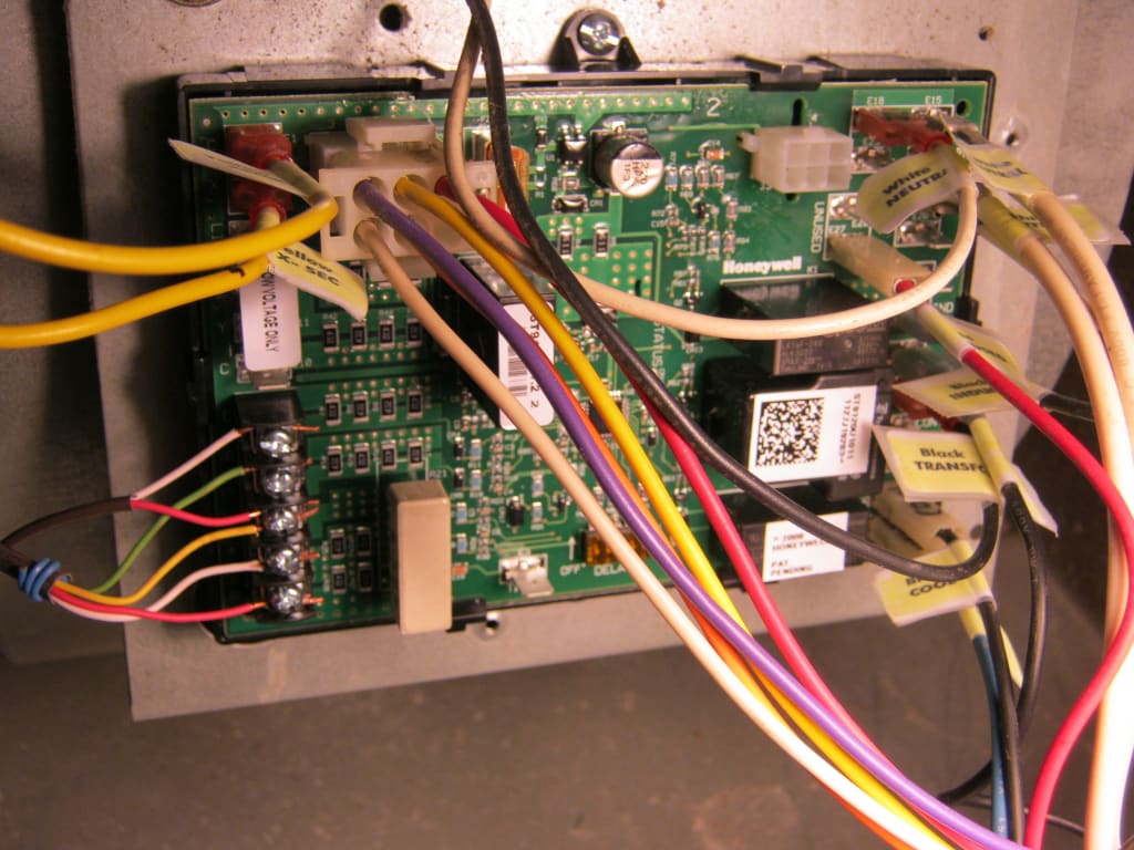
ST9120BU Wiring Conversion Instructions 1. When installing the ST9120U carefully check all appliance wires to make sure they are all connected to desired terminals at ST9120U. The common elements inside a wiring diagram are ground power source wire and connection output devices switches resistors logic gate lights etc.
Disconnect power before making wiring connections. Got it all figured out though and after a couple hot months the house is cool again. Some models include an enclosure.
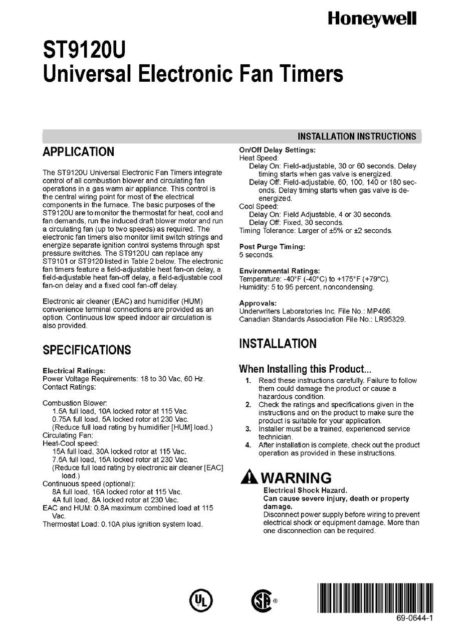
Take the two remaining white wires on the ST9101 wiring adapter and connect to Neutral quick con-nect terminals 3 and 4 on the ST9120U 5. The ST9120U Universal Electronic Fan Timers integrate control of all combustion blower and circulating fan operations in a gas warm air appliance. A wiring diagram is a streamlined traditional pictorial representation of an electric circuit.
Fits York Luxaire Coleman. N2Wiring for low-voltage two-position control M 3KΩ 0 OR 90-0 OR NA WIRING DIAGRAMS Actuator Wiring Diagrams Direct Coupled Actuators – Spring Return Models. This control is the central wiring point for most of the electrical components in the furnace.
I need a wire for wire to where every wire go on new style. 6 screws obtained locally. When installing the st9120u carefully check all appliance wires to make sure they are all connected to desired terminals at st9120u.
The instructions has Yorks st9120c2002 as one of the replacements but when looking at the diagram on page 7 it has a psc motor diagram the oem board has s1 s2 on the board going to tb2 which is 24v red wire 224 hot going into 16. To read a wiring diagram firstly you must know what fundamental elements are included in a wiring diagram and which pictorial symbols are used to represent them. Take the black wire on the ST9101 wiring adapter and connect to the S1 quick connect terminal on the ST9120U 6.
Identify the model number of the board being replaced and set the dip switches based on Table 2. Wiring compartment using four No. The furnace is a 1993 ICP.
Would have given 5 stars if not. This is a BRAND NEW OEM YORKLUXAIRECOLEMAN furnace Gas Valve Wiring HarnessThe YorkColemanLuxaire part is 024-31810-001 also S1-02531810001. Set operating mode to AUT O and switch on and off using the O VERRIDE button to ensure the system is operating correctly.
The new board does not use dip switch for setting times the Motor wiring colors did not match original two speed wiring. Board comes with instructions and several wiring harnessness to convert old plug designs into this updated board. Refer to Honeywell for wiring conversion diagrams.
Ok can someone help me with the wiring diagram from a st9120c 4057 to a st9120u. Incorrect wiring can lead to explosion hazard fire or equipment damage. Honeywell ST9120U 1011 universal electronic fan timer.
Wiring Make sure that all wiring complies with local codes and ordinances. Is it possible to connect an ecm motor to that board. 1 and 2 for standard wiring connections.
When installing the ST9120UB carefully check all appliance wires to make sure they are all connected to desired terminals at ST9120UB. See Wiring Guide document EN3H 2393 UK01 Completion Checklist f or Installation. Honeywell ST9120U 1011 electronic fan timer -.
Incorrect wiring can lead to explosion hazard fire. Carefully remove each wire and connect directly to the corresponding loca-tion on the new ST9120BU control board. Take the black wire on the ST9101 wiring.
We are the leading suppliers of domestic heating and combustion controls in the UK with products that include time temperature gas and water controls. 1 2 3 and 4 for standard wiring connections. Make sure that all wiring complies with local codes and ordinances.
The basic purposes of the ST9120U are to monitor the thermostat for heat cool and fan demands run the. Disconnect power before making wiring connections. Wiring CAUTION Explosion or fire hazard.
We need a wire to wire cross-reference for the controllers because we are unable to access their tech support. Honeywell ST9120u replacement fan timer. SalesPromotional Materials-Sell Sheet for Y8427U S8610U ST9120U S9200U Q3200U Universal Service Kit Promotion Distributors English SalesPromotional Materials-Brochure for Mid-Atlantic Inventory Management Guide Residential Combustion English.
The official UK site for Honeywell Home Heating Controls. Disconnect power before making wiring connections. This is a BRAND NEW Honeywell Furnace Control Circuit Board.

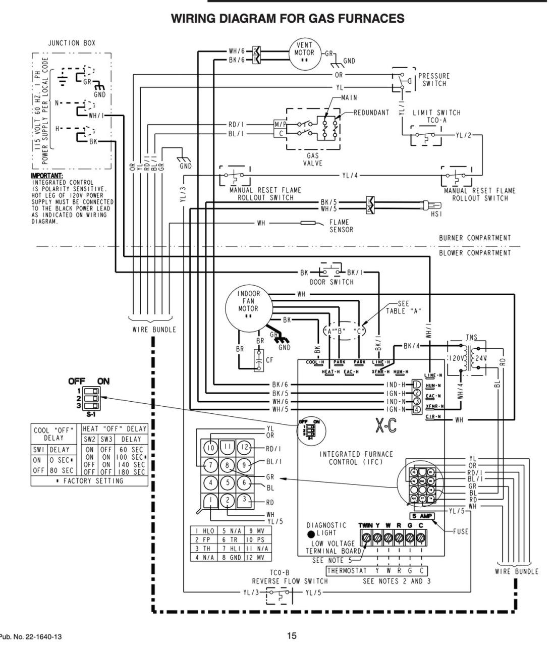
Wiring Diagram Of Old Furnace Board With A New Furnace Board

Resideo St9120u Universal Electronic Fan Timers Installation Guide Manuals

Resideo St9120u Universal Electronic Fan Timers Installation Guide Manuals
Honeywell St9120u Timer Manual Manualslib
St9120u1011 Resideo St9120u1011 Universal Electronic Fan Timer With Adjustable Heat

I Am Replacing A Havac Controller Where Do The S1 And S2 Wires Both Black On A St9120c 2002 Connect To On A

Fan Always Runs A C And Heater Never Do Doityourself Com Community Forums

Resideo St9120u Universal Electronic Fan Timers Installation Guide Manuals

Pdf St9120u Datasheet Universal Electronic Fan Timers

Resideo St9120u Universal Electronic Fan Timers Installation Guide Manuals
How To Install The Honeywell St9120u Furnace Control Board Youtube

Resideo St9120u Universal Electronic Fan Timers Installation Guide Manuals

St9120u1011 Overview Manualzz

Help No Blower In Auto Heat Mode Doityourself Com Community Forums

Resideo St9120u Universal Electronic Fan Timers Installation Guide Manuals
St9120u1003 Pdf Manualzz

Hvac Service Honeywell Ignition Control Replacement Youtube

Resideo St9120u Universal Electronic Fan Timers Installation Guide Manuals

Wiring Diagram Of Old Furnace Board With A New Furnace Board