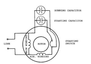
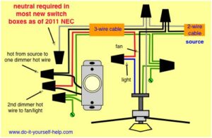
Need a wiring diagram. Its components are shown by the pictorial to be easily identifiable.
It shows the elements of the circuit as simplified shapes and the power as well as signal connections in between the gadgets.

Hydro flame furnace wiring diagram. Hydro flame furnace model fa 7916 installation manual. Atwood hydro flame furnace wiring diagram atwood furnace this article illustrates the gaps between schematics and circuit diagrams and may help you a good deal in identifying the constituents of a system distributing a circuit as well as fixing electrical equipment. Leave this manual with appliance.
Dc wiring diagram 5 illustrations. 1 atwood mobile products hydro flame user manual this instruction manual is for use by an authorized service technician to install an atwood hydro flame. Is the least efficient diagram among the electrical wiring diagram.
View online or download atwood hydro flame 8012 ii series service manual information manual. Collection of atwood furnace wiring diagram. Off black wire white wire thermostat any wiring replacement must be replace with equivalent type 105 c wire or better.
Wiring diagrams 7900 ii 8000 ii series. Atwood hydro flame 8012 ii series pdf user manuals. Water heater furnace ranges automobile parts cooktop.
Close the control access panel. Atwood hydro flame 33488 atwwod hydro flame 31501 fenwal 35 inside atwood furnace wiring diagram image size 600 x 391 px and to view image details please click the image. Oct 30 how to wire an atwood gas furnace model iv dclp.
Suburban rv furnace wiring diagram the wiring diagram intended for atwood furnace wiring diagram image size 835 x 684 px and to view image. See wiring diagram fig 5. A wiring diagram is a streamlined standard photographic depiction of an electric circuit.
What our users. Hydro flame furnace pdf manual download. Iii dc wiring ground electrode motor black yellow on off switch valve sail blw pwr yellow switch ignition board white limit switch.
Located outside of the furnace on the left side. Hydro flame tm furnaces by atwood lighting instructions all furnaces 7900 11 8012 11 8500 iv 8900 111. Hydro flametm 8500 iv series furnace models 8516 8520 8525 8531 8535 technical installation manual 9 warning fire or explosion if the information in this manual is not followed.
View and download atwood hydro flame technical installation manual online. Clearance to combustibles top. More atwood manuals.
Atwood hydro flame technical installation manual. Diagram color ford wiring coded1979 it is far more helpful as a reference guide if anyone wants to know about the home s electrical system.

Dometic 3316250 700 Single Zone Ct Thermostat Cool Furnace White Thermostat Heat Pump Thermostat Wiring

Atwood Hydro Flame Furnace 8500 Series Moreover Tankless Water Heater Diagram Besides Atwood Rv Furnace 8500 Parts Moreover Electric Hot W Diagram Flames Hydro

Image Result For Trimpot Pin Layout Layout Life Hacks Resistors

A Smokeless Flare Tip Design Eliminates Flame Lift Off At High Exit Velocities Ensuring Flame Stability And Efficient Combusti In 2020 Annular Prevention High Pressure

Animation How Four Stroke Engine Works Engineering Four Stroke Engine Animation

Digital Pool Heater Troubleshooting Guide Pool Heater Heat Installation Pool

Dometic 3316230 700 Single Zone Ct Thermostat W Control Board Cool Furnace White Heating Furnace Heat Pump Heat Pump Air Conditioner

Mobile Home Furnace Maintenance Troubleshooting Mobile Home Repair Mobile Home Furnace Home Furnace Furnace Repair

Atwood Hydroflame Furnace Model 8531 Iv Tune Up Kit Tekonsha Kit Tent Trailer

Rack And Pinion With A Hydroboost By Streetrodding Com Rat Rods Truck Rat Rod Ford Trucks

Best Water Hybrids Alternative Energy Free Energy Energy

Zen Wood Stoves Wood Burning Stoves Wood Gas Stove Wood Burning Stove Wood Stove

2492 Jpg 800 577 Hydro Hot Water Heater Rocket Stoves

Ammonia Plant Process Flow Diagram Of Single Train Section Front End With Three Controls Process Flow Diagram Process Flow Engineering Design

Coal Based Thermal Power Plants Thermal Boilers Thermal Power Plant Boiler Power Plant

All About Pellet Stoves Pellet Stove Pellet Heater Pellet Stove Inserts

2492 Jpg 800 577 Hydro Hot Water Heater Rocket Stoves

The Trompe An Almost Forgotten Air Compression System With Images Permaculture Energy Storage Northeastern Region


