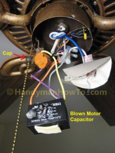
These connections are usually made at the time an entire system is installed or replaced and this is really the territory of a professional hvac. However some people still struggle with the wiring part of the motor to the capacitor.
Century Condenser Fan Motor Wiring Diagram Ac Condenser Basic Electrical Wiring Condensation
American standard heating air conditioning units feature time saving color coded wiring and.

Condenser wiring diagram. This is ac power and not a dual capacitor so the. This includes where to insta. Used for low ambient cooling to 30 f with txv.
Finally this guide is intended to be used as a general overview of common condenser unit wiring schematics. For a visual picture of typical wiring configurations reference the following guide. Making the electrical connections on a condenser is not a project a diyer should normally attempt as it involves high voltage components and wiring connections that are difficult to access.
Hvac condenser fan motor wiring diagram. The details from control wiring to the access panels. Switch that cycles the condenser off as indoor coil reaches freeze up conditions.
Points and condenser wiring diagram you will want an extensive expert and easy to understand wiring diagram. I ll provide a diagram and explain the wires below. Each part ought to be placed and linked to other parts in specific way.
Otherwise the arrangement won t work as it ought to be. Condenser fan motor permanent split capacitor grey green powdercoat 1 6 1 4 1 3 1 2 or 3 4 horsepower 208 230 vac 60 hertz 1 3 to 4 5 amps at rated speed and horsepower 370 vac 5 to 10 μf 30 18 awg 60 c 140 f equipped with an automatic thermal overload b 1075 rpm wiring for single speed shaft up shaft down or belly band 48. T40 tcu im 17 8 19 06 20.
Wiring diagram cross reference condensing unit voltage evaporator voltage and type condensing unit type diagram number page diagram. As always refer to the wiring diagram on the particular motor you are using. All installers should follow the wiring diagram attached to the equipment electrical compartment cover.
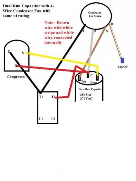
White wire from the condenser fan motor to one side of power on the contactor t1 and jumped to one side of the fan capacitor. Here s the 3 wire method. With this sort of an illustrative manual you are going to be able to troubleshoot prevent and complete your assignments easily.
Some condenser fan motors wire to a circuit board while others use proprietary plugs for their connectors. Points and condenser wiring diagram briggs and stratton points and condenser wiring diagram points and condenser wiring diagram points condenser coil wiring diagram every electric arrangement consists of various different components. How to wire a run capacitor to a motor blowers condensers sometimes when a blower or condenser fan motor goes bad a technician or even a diyer has issues wiring the new motor and capacitor most motors come with clear instructions or a wiring diagram on the side.

Need Help Replacing Hvac Condensor Fan Motor 3 Wire Old To 4 Wire New Ceiling Fan Wiring Ceiling Fan Switch Fan Motor

Ac Wiring Diagram Of Window Airconditioner Ac Wiring Thermostat Wiring Wire

Trane Xl 1200 Wiring Diagram Nordyne Condenser In Xl1200 Heat Pump Regarding Trane Wiring Diagram Trane Heat Pump Thermostat Wiring Heat Pump

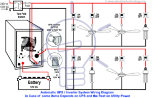
Electrical Wiring Diagrams For Air Conditioning Systems Part Two Electrical Knowhow Electrical Wiring Diagram Ac Wiring Electrical Diagram

Blower Motor Wiring Diagram Ac Condenser Fan Motor Wiring Diagram In 2020 Air Compressor Pressure Switch Exhaust Fan Industrial Refrigerator Compressor

Wire A Thermostat Thermostat Wiring House Wiring Home Electrical Wiring

Ac Dual Capacitor Wiring Diagram Ac Capacitor Electrical Circuit Diagram Diagram

Wiring Diagram For Ac Unit Elegant Goodman Condenser Wiring Electrical Circuit Diagram Electrical Wiring Diagram Ac Wiring

Magnetic Contactor Schematic Diagram Electrical Circuit Diagram Thermostat Wiring Electrical Wiring Diagram

Electrical Wiring Diagrams For Air Conditioning Systems Part One Electrical Knowhow Electrical Diagram Air Conditioning System Electrical Wiring Diagram

Air Compressor Capacitor Wiring Diagram Before You Call A Ac Repair Man Visit My Blog For Some Capacitors Electrical Wiring Diagram Electrical Circuit Diagram

Ac Dual Capacitor Wiring Diagram Ac Capacitor Electrical Circuit Diagram Refrigerator Compressor
Air Conditioner C S R Wiring Diagram Compressor Start Full Wiring Fully4world Refrigeration And Air Conditioning Air Conditioner Compressor Air Conditioner

Ac Condenser Fan Motor Wiring Diagram 4 Wire Beautiful For New 7 Fan Motor Ceiling Fan Wiring Electrical Circuit Diagram

Unique Wiring Diagram Ac Blower Motor Diagram Diagramtemplate Diagramsample

5 Pin Bosch Relay Wiring Diagram Fitfathers Me Electrical Circuit Diagram Thermostat Wiring Electrical Wiring Diagram

Heat Pump Condenser Fan Wiring Diagram Electrical Diagram Ac Wiring Electrical Wiring Diagram

Wiring Diagram Symbols Chart Split Air Conditioner Wiring Diagram Hvac Condenser Wiring Diagram Fres

Starting Capacitor Wiring Diagram With Single Phase Motor Start At Electrical Circuit Diagram Circuit Diagram Capacitors