The switch may or may not be used as double pole its being used as its 20A. Wiring diagrams residential electric water heaters current production 315267 000 time clock switch operates bottom element only to power supply to time clock switch off peak meter operates to power supply to off peak clock 2 wire 1 phase non simultaneous operation from 3 wire heater junction box black blue yellow to off peak.
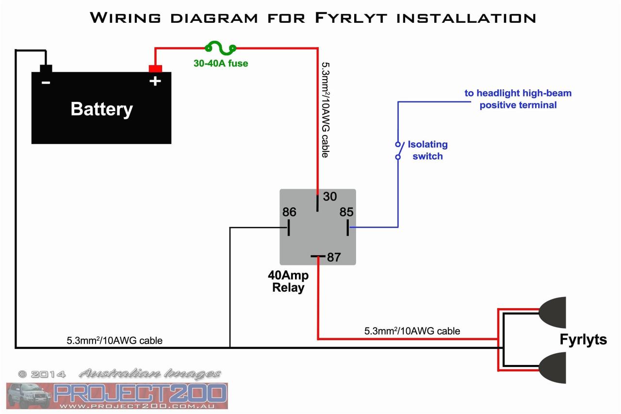
Best Bosch Relay Wiring Diagram 5 Pole Electrical Outlet Symbol 2018 Electrical Circuit Diagram Light Switch Wiring Electrical Wiring Diagram
Wiring Diagram For Bathroom Heater Fan Light.

Heater Switch Wiring Diagram. 2 way heater switch wiring diagram. The other goes thru the resistor to the middle post on the switch. Pir motion sensor switch 85-265v led adjustable pir detector infrared motion sensor switch auto on.
Single Phase AC circuits where line voltage and current do not exceed thermostat rating. Wiring diagrams residential electric water heaters current production 315267 000 time clock switch operates bottom element only to power supply to time clock switch off peak meter operates. Assortment of water heater timer wiring diagram.
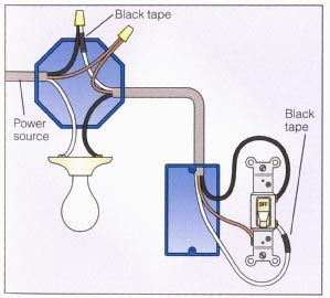
The electricity flows from the hot wire black through the 2-way switch shown in off position and then to the light and returns through the neutral wire white. Collection of atwood hot water heater wiring diagram. Read the schematic like a new roadmap.
Water Heater Wiring Diagram Hot Water Heater Repair. A wiring diagram is a simplified standard photographic representation of an electrical circuit. Wiring Diagram Electric Water Heater Best Electric Water Heater.
Double pole switch wiring way heater lighting diagram water 2 schneider electric pieno 20a vivace geyser theop power tech trendiswitch wylex dual point immersion switches c electrical work answer help with 3 malliatm 20 ax dp dressable using a. Circuit does not have a positive off. Assortment of chromalox immersion heater wiring diagram.
There is not much to the wiring in the. 2 way heater switch wiring diagram. You simply require to have a excellent comprehension on.
It represents the physical parts of the electric circuit as geometric shapes with the real power and also connection links between them as thin edges. 1 trick that We. These three in one fixtures work best when wired to a three function switch box allowing for individual control of the units functions from a single point.
Before reading the schematic get acquainted and understand all the symbols. Print the wiring diagram off plus use highlighters to trace the signal. One wire from the motor is grounded.
Motor home rapidly switch lanes. Circuit 2 Way Switch Wiring Diagram Home. When you make use of your finger or perhaps the actual circuit with your eyes it is easy to mistrace the circuit.
Vl_9967 heater wiring diagram also wiring a 3 way switch with motion sensor wiring diagram. Angelo on December 21 2021. Look at this diagram from JBGs website.
Mr Heater Thermostat Wiring Diagram Source. Pin On Diagram Sample. On the back of the heater box there should be a resistor.
18 Inch Immersion Heater Dual Safety Thermostat With Resettable Cut Out. In the following water heater wiring diagram a 3000 Watts single heating element is shown connected to 120V AC as well as 240V AC. Timer Testing Wiring Diagram Earth Bondhon Timer Digital Timer Diagram.
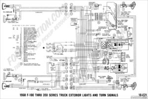
1957 Chevy Electrical Wiring Diagrams Heater welcome to my website this article will discuss concerning 1957 Chevy Electrical Wiring Diagrams Heater. Connect the black fan wire to the black wire in the 3 cable. The gas burner lights automatically when the hot water tap is opened and goes out when the tap is closed.
Wiring diagrams residential electric water heaters current production 315267-000 time clock switch operates bottom element only to power supply to time clock switch off peak meter operates to power supply to off peak clock 2 wire 1 phase non simultaneous operation from 3 wire heater junction box black blue yellow to off peak or 3 phase power supply. 2 Way Heater Switch Wiring Diagram. Three Phase AC heater circuit where line voltage and current do not exceed thermostat rating.
WIRING DIAGRAM BLACK WHITE N 120VAC Control circuit from Time Switch 120VAC 208VAC 277VAC 480VAC 120VAC 208VAC 277VAC 480VAC 5401 Control circuit from Time Switch Wire other circuits B C and D respectively 120 to 480VAC Keep low voltage wires inside this compartment. See also Smith Water Heater. Best 220 Volt Baseboard Heater Thermostat Wiring Diagram The 20 7 240 Volt Heater Wiring Diagram Wiring Diagram contains many detailed illustrations that display the link of varied things.
Assortment of atwood water heater switch wiring diagram. I print out the schematic in addition to highlight the signal Im diagnosing in order to make sure I am staying on right path. My electric heater just didnt work this year when I turned it on.
Typical Heater Wiring Diagrams The following diagrams show typical heater wiring schematics. Propane Rv Water Heater Switch Wiring Diagram. It is wired into the wiring for the heater.
It shows what sort of electrical wires are interconnected and may also show where fixtures and components could be connected to the system. It consists of guidelines and diagrams for various varieties of wiring strategies along with other items like lights windows and so forth. It is really easy to draw a wiring diagram.
A wiring diagram is a simplified standard photographic depiction of an electric circuit. The switches didnt light up and there was no heat. READ Wiring Diagram For 2016 Rv Water Heater Collection.
Read Wiring Diagram For Immersion Heater Switch PDF on our digital library. We have actually accumulated lots of pictures hopefully this image serves for you and assist you in discovering the response you are searching for. The wall switch box and.
Check for blown fuses or tripped breaker 2. Iuk Electric Power Control System Full House Wiring Diagram Using Single Phase Line Energy Meter Facebook. Heater 5 Pin Switch Wiring Diagram Wiring Diagram is the visual representation of a complicated electric circuit.
A wiring diagram is a streamlined standard pictorial representation of an electric circuit. Typical Heater Wiring Diagrams The following diagrams show typical heater wiring schematics. Diagram of immersion heater wiring.

Push Button Ignition Switch Wiring Diagram New Boat Wiring Kill Switch Electrical Wiring Diagram

Lovely Wiring Diagram Alternator Diagrams Digramssample Diagramimages Wiringdiagramsample Wiringdi Electrical Circuit Diagram Voltage Regulator Alternator

Intertherm Thermostat Wiring Diagram Wiring Forums Diagram Diagram Chart Electrical Wiring Diagram

55 New Potential Relay Wiring Diagram Electrical Circuit Diagram Ac Capacitor Electrical Diagram

Unique Single Phase Capacitor Start Capacitor Run Motor Wiring Diagram Electrical Wiring Diagram Electrical Circuit Diagram Capacitor

Square D Motor Control Center Wiring Diagram Well Pump Pressure Switch Diagram Wire
Light Switch Wiring Diagram Multiple Lights Home Electrical Wiring Light Switch Wiring Installing A Light Switch

Installation Of Single Pole 3 Way 4 Way Switches Wiring Diagram Electrical Wiring Home Electrical Wiring Electrical Switch Wiring

Diagram 240v Airpressor Wiring Diagram Full Version Hd Electrical Circuit Diagram Air Conditioner Maintenance Electronic Parts

Nordyne Hvac Wiring Diagrams Schematics In Furnace Diagram In E2eb 015ha Wiring Diagram Electric Furnace Furnace Gas Furnace

Lovely Y Plan Wiring Diagram Combi Boiler Diagrams Digramssample Diagramimages Check More At Https Nostoc Co Y Plan Wiring Diagram Com Diagram Boiler Wire

3 Way Switches Electrical 101 Light Switch Wiring Electrical Wiring Diagram Three Way Switch

Water Heater Wiring Diagram Hot Water Heater Repair Water Heater Repair Water Heater Thermostat

Lewmar Windlass Wiring Diagram Upgrade Windlass Power Wiring Of Lewmar Windlass Wiring Diagram With Windlass Wiring Diagram For Windlas Diagram Power Wire Wire

On Off Switch Led Rocker Switch Wiring Diagrams Oznium Boat Wiring Automotive Electrical Automotive Repair

Relay Wire Diagram 5ab7826eea718 In 12 Volt Relay Wiring Diagram Electrical Circuit Diagram Circuit Diagram Electrical Diagram

Alternate 4 Way Switch Wiring Diagram Light Switch Wiring 4 Way Light Switch 3 Way Switch Wiring

Unique Trane Heat Pump Thermostat Wiring Diagram Thermostat Wiring Electrical Diagram Trane Heat Pump

3 Way Switch Wiring Diagram Light Switch Wiring 3 Way Switch Wiring Wiring A Plug