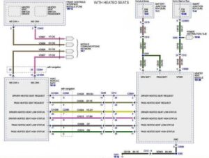
Step 3 Wiring Select the wiring diagram through. PAGE 1 UNIVERSAL COMPATIBILITY.
Hydrolevel Vxt 24 Instructions Pdf Download Manualslib
The wiring diagrams show connecting the RB-24 on typical burner circuits.
Vxt 24 Wiring Diagram. The feeder is a 24 VAC non-rising float valve for steam boilers. 24 VAC Operating Voltage. Save these instructions for future reference.
Safgard model oem 24td float style control honeywell model rw 700 guard ring. Model CG foam-compensating Low Water Cut-Off for steam boilers. Hydrolevel Water Feeder 4567 is a straight thru 1-10 gallon per minute water feeder.
Connect a wire from terminal H on the feeder to the burner circuit hot. Hydrolevel VXT-24V – Automatic Water Feeder – 24V – The Hydrolevel VXT steam boiler water feeder offers the homeowner the convenience of maintaining a safe water line in the boiler automatically. TheVXT can be set to feed to the level of the low water cut-off or can be set from 1 to 5.
I can do manual feed by using FEED button but it is not automatically feeding boiler. ModelVXT-24 WARNING To preventelectrical shockorequipment damagepower mustbeoffduring installationorser-vicingofthecon – trolToprevent. Step 3 Wiring Select the wiring diagram through below that corresponds to the low water cut-off installed on the boiler.
– Did not work although I did see red light in LWCO. I have attached wiring diagram between Hydro Level VXT-24 Auto Feeder and McDonnell PS-820-24 LWCO. Basic Wiring McDonnell Miller The RB-24 can be used on gas and oil fired boilers with 24 volt control circuit including boilers with spark ignition.
Serious burns the boiler should be thoroughly cooled before installing or servicing control. We hot wired it to make sure it would fire off it did. A wire from terminal H on the water feeder to the hot side of the.
All Steamed Up Inc. Steam Boiler Water Feeder VXT-24 Valve FAQs Diagnostic maintenance questions about the Hydrolevel VXT-24 water feeder valve. The feeder has an insulated steam chamber that contains an adjustable floating level that automatically controls water flow.
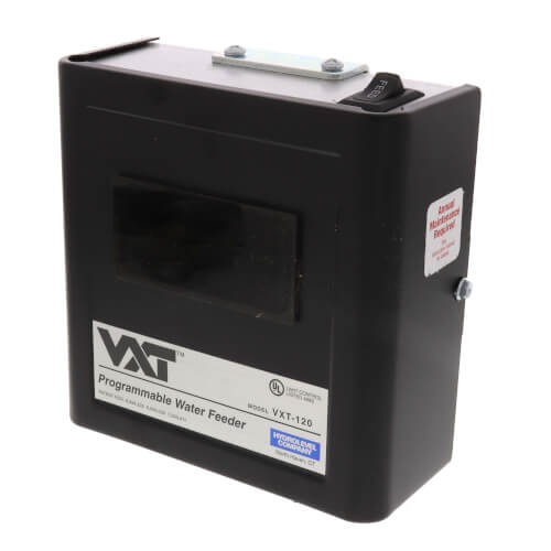
Programmable Water Feeder for Steam Boilers. For this 24-volt feeder you want 18-gauge thermostat wire at minimum. 1 Reduced water level to lowest to call for Water from Auto Feeder.
Cycle Guard Cg400 Lwco Wiring Diagram. Model VXT-24 LIMITED MANUFACTURERS WARRANTY. Series 69 Low Water Cutoff with MM Model A Electronic Water.
Step Wiring Select the wiring diagram below that corresponds to the low water cut-off installed on the boiler. But it theres any chance the wire could be abused BX is the way to go. Model VXT-24 LIMITED MANUFACTURERS WARRANTY.
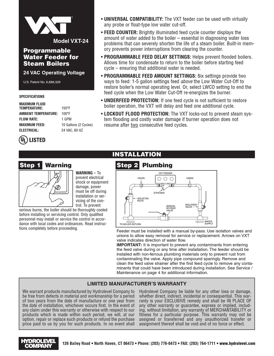
Feeder must be installed with a manual by-pass. Shown Discussed here. Water Feeder Wiring Diagram – Another Blog About Wiring Diagram step 3 wiring mcdonnell miller ps series hydrolevel vxt 24 rh manualsdir com wfe water feeder wiring diagram vxt water feeder wiring diagram.
Arrow on VXT valve indicates direction of water flow. You likely have a new furnace t. The VXTs built-in feed counter records the number of gallons that enter the boiler during automatic feed cycles or if the FEED.
24 VAC Operating Voltage US. The same as the LWCO and burner circuit voltage. Manufacturers schematic does not exist or is not available from the boiler.
WARNING To prevent electrical shock or equipment damage power must be off during installation or ser-vicing of the con-trol. All information in this publication is based on the latest production information available at the time of approval for. For all cycles on the WFE the feeder will stop.
If make-upwater is required after the delay period the VXT will initiate a feed cycle. Dential hot water boilers C. Step 3 wiring Mcdonnell miller Ps-800 series Hydrolevel VXT-24 User Manual Page 2.
6688329 INSTALLATION Model VXT-24 WARNING To. Brightly illuminated feed cycle counter displays the amount of water added to the boiler essential in diagnosing water loss problems that can severely shorten the life of a. Consult boiler manufacturers.
MV models are rated at 24 VA 24 VAC to VAC feeder. Vxt 24 wiring diagram. Connect a wire from terminal H on the feeder to the burner circuit hot.
When using alternative wiring diagram the boiler oper ating control s zc terminal will see the load of the circulator s. Upon a feed signal from low water cut-off the VXT feeder delays from 30 seconds to 10 minutes to allow condensate to return to boiler. Luckily there are some places that may have just what you need.
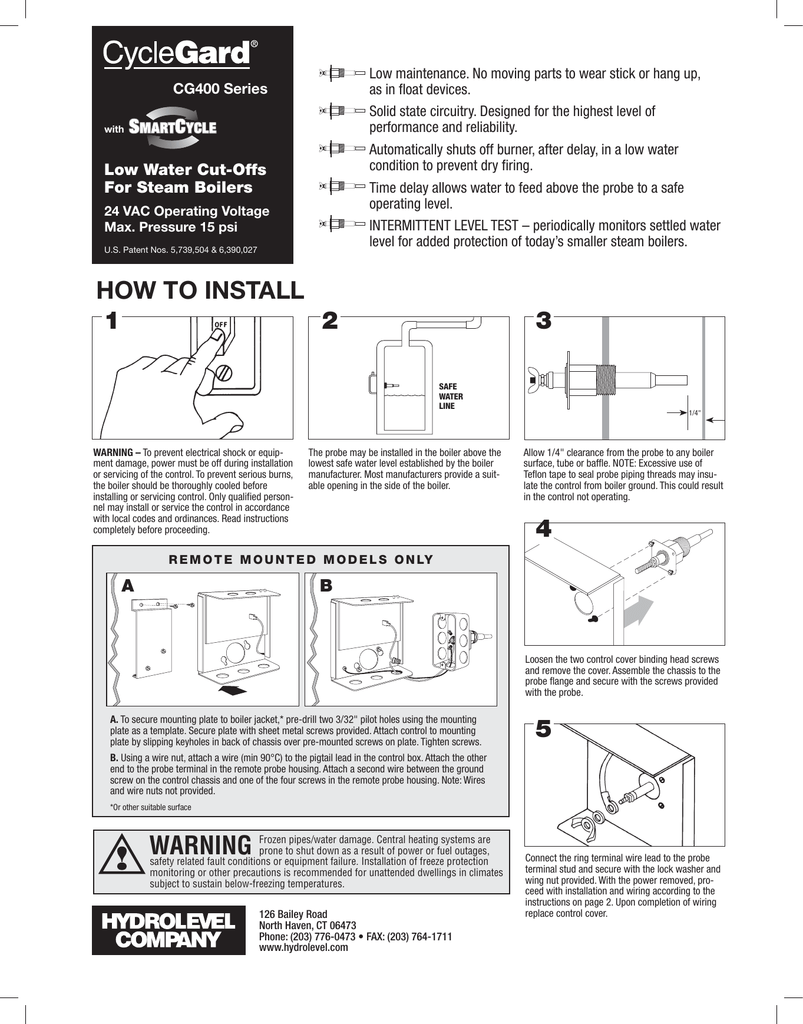
How to wire your Cyclegard low water turnoff to your water feeder. NOTE Hydrolevel CG Connect the ring terminal wire lead to the probe terminal. Wiring diagram ct90k0k1 wiring diagram k2 thru k6 ct90 wiring diagram 1977 ct90 s90 us imported wire diagram s90 s90 st90 1980 1981 ct110.
In addition to this added convenience The VXT is the first automatic steam boiler water feeder designed to monitor the amount of water added to a steam boiler. The Hydrolevel VX-24 24-volt programmable water feeder valve for steam boilers. Hydrolevel VXT-24 24 volt water feeder with digital feed counter programmable feed delay setting programmable feed amount settings manual feed button underfeed protection and lock-out flood protection.
I have tried below. Model VXT-24 WARNING To prevent electrical shock or equipment damage power must be off during. Step 3 Wiring Select the wiring diagram through below that corresponds to the.
Electric Water Feeder Before using this product read and understand instructions. This automagic water feeder is described by the manufacturer as a universal control that can be used with. First- KILL THE POWER TO FURNACE WHILE YOU WORK.
Page 1 universal compatibility. 26 or 24 AWG if memory serves. Mcdonnell miller 67 wiring diagram Wfe 24 Water Feeder Wiring Diagram Awesome Vxt Water Feeder Wiring Diagram Vxt Water.
Step 3 Wiring Select the wiring diagram through below that corresponds to the low water cut-off installed on the boiler. VXT-24 Instructions Created Date. Step 3 Wiring.
The VXT feeder can be used with virtually any probe or float-type low water cut-off. Safgard model oem-24td Float style control Honeywell model rw-700 guard ring. Inspectors here seem to be OK with that as long as its properly secured.
Upon receiving a feed signal from a low water cut-off the VXT water feeder delays from 30 seconds to 10 minutes to allow condensate to. The Hydrolevel VXT-24 the new gas line with its new shut off valve the flue connector is in. Note that the control requires a constant source of power with the red hot and white.
Do not connect power to n and h terminals. Model VXT-24 Programmable Water Feeder for Steam Boilers FEED COUNTER.

Vxt 24 120 Residential Steam Water Feeders Hydrolevel

Vxt 24 120 Residential Steam Water Feeders Hydrolevel
2

Step 3 Wiring Mcdonnell Miller Ps 800 Series Hydrolevel Vxt 24 User Manual Page 2 4
Hydrolevel 45 410 24v Low Water Cut Off For Cg400 1090 Steam Boiler Installation Manual Manualzz

User Manual For Crown Boiler Bsi207 A User Manual Servicing Manual Settings And Specifications Ofcrown Boiler Bsi207 Page 18 User Manuals And Advice For Your Devices User Manual Info
Vxt 24 120 Residential Steam Water Feeders Hydrolevel

Newly Installed Vxt 24 Water Feeder Not Working Heating Help The Wall

Vxt 24 New Gas Line Final Tweaks Ready To Wire Fire Youtube

Hooking Up And Testing A Vxt 120 Hydrolevel Water Feeder On A Steam Heating Boiler Youtube

Hydrolevel Vxt 24 Is Not Feeding Water Steam Boiler Doityourself Com Community Forums

Newly Installed Vxt 24 Water Feeder Not Working Heating Help The Wall

Hydrolevel Vxt 24 Is Not Feeding Water Steam Boiler Doityourself Com Community Forums

Hydrolevel Vxt 24 Is Not Feeding Water Steam Boiler Doityourself Com Community Forums
45 122 Hydrolevel 45 122 Vxt 120 Water Feeder 120v

Hydrolevel Vxt 24 User Manual

Vxt 24 120 Residential Steam Water Feeders Hydrolevel
Vxt 24 Floods A Steam Boiler But It S Not The Vxt S Fault Youtube

Hydrolevel Vxt 120 V1 User Manual