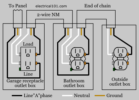
Gfci outlet wiring method this article and the electrical wiring diagram will show you how to install a gfi using the feed through method which will protect more than one outlet. Loosen the silver and brass terminal screws on the line side of the outlet.
Gfci Outlet Wiring Outlet Wiring Gfci Home Electrical Wiring
If more than 1 black and 1 white conductor are in the electrical box also loosen the load side silver and brass terminal screws.

Gfci outlet wiring diagram. Gfci outlet wiring diagram. Wiring a gfci outlet and a light switch. The source hot wire is spliced with one of the switch wires and the other switch wire is connected to the hot line terminal on the device.
Refer to the diagram above about wiring gfci receptacles for additional help. In this diagram the switch built into the combo device is wired to control the gfci outlet itself. Gfci wiring method article shows outlet wiring a gfi using the tailed method.
In the gfci mainly two wires connect as also shown in a diagram the current flowing from the source and coming back are some due to current laws. This diagram illustrates wiring a gfci receptacle and light switch in the same outlet box a common arrangement in a bathroom with limited space. To wire a gfci circuit breaker see this link and wire a gfci switch combo at this link.
The source neutral is connected the line neutral terminal. Wiring for a switch and gfci receptacle in the same box is also shown. It means all the connected loads to the load terminals of gfci are protected.
Wiring diagram for a switched gfci combo outlet. So gfci designed as checking the difference between the current leaving and returning through current transformer of the gfci to protect device exceeds 5ma. Wiring a gfci outlet with combo switch outlet receptacle light switch.
In this gfci outlet wiring and installation diagram the combo switch outlet spst single way switch and ordinary outlet is connected to the load side of gfci.

Wiring Diagram Of A Gfci To Protect Multiple Duplex Receptacles Home Electrical Wiring Diy Electrical Outlet Wiring

Electrical Gfci Outlet Wiring Diagram Outlet Wiring Gfci Electrical Wiring

Electrical Outlet Wiring Diy Electrical Home Electrical Wiring

How Do I Replace A Gfci Receptacle In My Bathroom Electrical Wiring Outlet Wiring Gfci

Diagram Of A Circuit Breaker Gfci Diagram Electrical Panel Wiring

Multiple Gfci Outlet Wiring Diagram Outlet Wiring Home Electrical Wiring Electrical Wiring

Gfci Outlet Wiring Diagram Outlet Wiring Home Electrical Wiring Electrical Wiring Colours

Gfci Wiring With Unprotected Switch And Light Gfci Home Electrical Wiring Electrical Wiring

Wiring Diagrams Multiple Receptacle Outlets Outlet Wiring Home Electrical Wiring Gfci

Gfci Circuit Breaker Wiring Gif 500 327 Home Electrical Wiring Diy Electrical Electrical Breakers

Multiple Gfci Outlet Wiring Diagram Outlet Wiring Electrical Wiring Gfci

Wiring Diagram Outlets Beautiful Wiring Diagram Outlets Splendid Line Wiring Diagram Help Signalsbrake Light Code For Wire Switch Gfci Light Switch Wiring

How To Wire A Gfci Circuit Breaker Circuit Electrical Outlets Residential Electrical
Wiring Diagram For A Ground Fault Circuit Interrupter Outlet Wiring Basic Electrical Wiring Home Electrical Wiring

Wiring Diagram For Two Gfci Electrical Wiring Electricity Home Electrical Wiring

Gfci Outlet Wiring Diagram Outlet Wiring Electrical Wiring Home Electrical Wiring

Gfci Receptacle And Switch Same Box Electrical Wiring Home Electrical Wiring Outlet Wiring

Wiring Diagrams Multiple Receptacle Outlets Outlet Wiring Home Electrical Wiring Gfci

Wiring Diagrams For Ground Fault Circuit Interrupter Receptacles Www Do It Yourself Help Com Gfci Home Electrical Wiring Electrical Wiring