The new parallel breakout board appears a bit different but the process of wiring and testing is the same. The wiring of the parallel breakout board from the output terminals to the driver digital pulse step pulse and direction lines are explained.
Wire Limit Switches Diy Cnc Router Cnc Machine Design Cnc Router Plans
I need help wiring my limit switches on my cnc that i bought on ebay.

Cnc limit switch wiring diagram. Noise generated by plasma cutters etc. I am putting up pictures so that someone can help. Open loop means that there is no feedback to the controller.
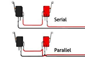
Mach3 knows where all the switches are. There are 6 limit switches 3 are red and 3 are gray. Wiring the limit switches these instructions will explain how to wire the limit switches for x y and z axis s.
Limit switches are used to let you software know when an axis has come close to or is at the limit of it s physical movement. Wiring home and limit switches gnea grbl wiki github will1384 s shapeoko 2 page the forum homing using nc class b project switch options smithy detroit machine tools dn 8040 diagram cnc cabling wiring home and limit switches wiring limit switches wiring limit switches gnea grbl wiki github wiring home and limit switches will1384 s shapeoko 2 page read more. The purpose of the limit switch is to send a signal that will stop the axis from trying to move past the end of its travel range.
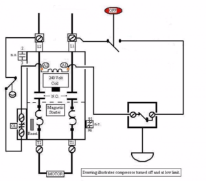
A cnc can have one or two limit switches per axis. During homing it first moves the z until encountering a switch recognizes home and backs off a trifle to close the switch. During a cutting operation if it encounters a switch it assumes it to be a limit and shuts down.
Limit switch or e stop signals in very noisy environments or industrial premises it can help reduce transients capable of damaging your electronics. Will require filtering to allow stable operation of your cnc or automated machinery. Cnc limit switch wiring diagram wiring diagram is a simplified up to standard pictorial representation of an electrical circuit it shows the components of the circuit as simplified shapes and the aptitude and signal contacts in the company of the devices.
Go to the new parallel breakout board to get more information and the wiring diagram. There is a limit switch on top and bottom of the z axis on the right and left side of the x axis front and back of the y axis. Limit switches have an advantage in open loop system.
Wiring diagram for power supplies v pos v c v com gnd l n l n l n.

Cnc Wiring Diagram Recherche Google Diy Cnc Cnc Plasma Cnc

Cnc Grbl Limit Switch Wiring The Ultimate Solution In 2020 Cnc Arduino Cnc Solutions

How To Make Grbl Cnc V3 Shield Based Mini Cnc Machine From Scrap Dvd Drive Arduino Cnc Cnc Maschine Zeichenmaschine

Wire Limit Switches To Jk02 M Cnc Router Plans Cnc Machine Cnc Router

Pin On Diy Cnc Router

2 Limit Switches Wiring Using Same Pin Arduino Arduino Arduino Programming Arduino Projects

Wire Limit Switches To Jk02 M Diy Cnc Cnc Software Diy Cnc Router

Usb Cnc Controller Schematic Cnc Controller Cnc Diagram

R Cnc Wiring Makerfr Diy Cnc Router Diy Cnc Cnc

Overview Since We Made The Tutorial On How To Control A Stepper Motor Using An Analog Joystick We Ve Gotte Arduino Stepper Motor Arduino Stepper Motor Control

Cnc Wiring Diagram Diy Cnc Router Cnc Controller Diy Cnc

Wire Limit Switches Arduino Cnc Diy Cnc Router Cnc Controller

Wiring Limit Switches Arduino Tutorial Arduino Arduino Projects Arduino Programming

Https Www Probotix Com Diagrams 3 Axis Probostep Wiring Dia Jpg Diy Cnc Router Diy Cnc Cnc Router

Usb Cnc Controller Schematic Cnc Controller Cnc Diagram

Wire Limit Switches To Jk02 M Diy Cnc Router Diy Cnc Cnc Machine Projects

Cnc Breakout Board Wiring Diagram Cnc Controller Breakout Board Cnc Spindle
Wire Limit Switches Diy Cnc Router Cnc Controller Arduino Cnc

Wiring Up Limit Switches On A Cnc 3020t Engraving Router Cnc Arduino Cnc Cnc Projects