If you have a Unipolar drive the terminal will be labeled A B C D and AC Common BD Common or comm Notes. Otherwise the arrangement will not function as it should be.
Fresh Wiring Diagram Inverter Diagrams Digramssample Diagramimages Wiringdiagramsample Wiringdiagram Thermostat Wiring Ac Wiring Electrical Wiring Diagram
4-Wire Stepper Motors.

4 Wire Bipolar Stepper Motor Wiring Diagram. Bipolar Stepper Step Angle. Connect Wires with Wire Nut WhiteRed WhiteYellow Phase 1 A Black WhiteOrange Phase 3 A Orange WhiteBlack Phase 2 B Red WhiteYellow 4 Lead Bipolar Parallel MBC or MLP Series Phase 4 B Yellow WhiteRed Phase 1 Black Phase 3 Orange Phase 2 Red Phase 4BLD TM Series Yellow COMMON Phase 1 3 WhiteBlack WhiteOrange 6 Lead Unipolar. Stepper Motor Basics 4 Wires Bipolar Motor Youtube 4 Wire Motor Wiring Diagram In addition Wiring Diagram provides you with the time body by which the projects are for being finished.
Note however that if you are using the Pololu standard connections they have the phases ordered. If your stepper motor has 4 wires it is a bipolar stepper motor. Hobbytronics Nema 34 Stepper Motor.
For instance if a module is usually powered up and it sends out a new signal of half the voltage and the technician will not know this he would think he has a challenge as he would. Each component ought to be set and connected with different parts in specific way. There are slight differences on how the different variant of stepper motors work ie.
Stepper Motor wiring. 1B 1A 2A 2B. Whats people lookup in this blog.
Stepper motor specifications for a NEMA 17 four phase degree step per The Motor Wiring Diagram also illustrates the order of the stator poles in the. Determine how many lead wires your motor has 4 6 or 8 wires. Nema 23 stepper motor pinout features and example with arduino nema 23 stepper motor datasheet specs applications nema 23 stepping motor 24 0 kg cm 4 wire 57bygh310 nema 23 stepper motor bipolar 1 8 degree 3a 2 phase 4 wires ato com.
Indicates that the particular wire is not connected to the drive. Bipolar stepper motors have two windings which are not connected to each other wired internally like this. A stepper motor controller with driver circuit.
4 Wire Motor Wiring Diagram 4 wire ac motor wiring diagram 4 wire blower motor wiring diagram 4 wire condenser fan motor wiring diagram Every electric arrangement is composed of various different components. Learn how to wire 4-wire stepper motors with the Buildbotics CNC controller. 18 deg Holding Torqu.
Nema 23 Stepper Motor Wiring Diagram. There are slight differences on how the different variant of stepper motors work ie. But today I can say that this type of engine.
4 Wire Stepper Wiring Jpg Chipkit. The 6V 08A 2 phase NEMA 17 bipolar stepper motor is a 4-wire bipolar stepper motor with 18per step specified to have a holding torque of 44oz-in. The trick is figuring out which wires make up the coil pairs.
This is a common word during discussions involving peculiarities of step motors which can have 4 5 6 and 8 wires. Stepper motors with six wires are unipolar and have one winding per phase like the bipolar steppers but with a center tap. For more information on wiring stepper motors check out our wiring guide https.
These days most of the time its Red Blue Green Black in that order. Stepper Motor Wiring Diagram arduino stepper motor wiring diagram cnc stepper motor wiring diagram leadshine stepper motor wiring diagram Every electrical structure is composed of various distinct pieces. These cables are color coded such that the A wire is red the A- wire is black the B wire is yellow and the B- wire is purple.
It has 4 wires each phase draws 28A with holding torque 126Nm 1784ozin. Stepper Motor Wiring. For example if using the above 4 wire motor with color code 1 the Red wire would be connected to A Blue connected to A Green connected to B and Black connected to B.
The 4 wires 5 wires and 6 wires stepper motors. 4 Wire Stepper Motor Connection Diagram wiring diagram is a simplified suitable pictorial representation of an electrical circuit. Wiring diagram for ULN2003 driver with 28BYJ-48 stepper motor and Arduino.
4 wire stepper motor wiring diagram. Each component should be set and connected with different parts in particular manner. STEPPER MOTOR BASICS – 4 WIRES BIPOLAR MOTOR example.
So for that connection you want the. Stepper Motor Nema 17 Size 200 Steps Rev 12v 350ma Id 324 14 00 Adafruit Industries Unique Fun Diy Electronics And Kits. Nema 17 Stepper Motor 2 4 Kg Cm Wire 42bygh011.
The 4 wires 5 wires and 6 wires stepper motors. If not the structure wont function as it should be. 4 5 6 and 8 wire stepper motors.
Connecting 4-wire stepper motors requires connecting A and A- to one of the motor coils and B and B- to the other motor coil. 3-wire radiator fan motor. 5-wire stepper motor wiring diagram.
Red and Blue are the first coil Green and Black are the second and if you wire them to the driver in that order it will just work. While many motors take advantage of 6- and 8-wire configurations the majority of bipolar one winding per phase stepper motors provide four wires to connect to the motor windings. If your stepper motor has 4 wires it is a bipolar stepper motor.
In this tutorial you will learn how to control a stepper motor with the TB6600 microstepping driver and Arduino. The basics on how stepper motor stepper controller and stepper driver work. Electrical Specification Manufacturer Part Number.
A basic 4-wire stepper motor is shown in Figure 1. Youll be able to learn exactly if the projects ought to be completed which makes it easier to suit your needs to effectively handle your time and. Since coils A and B on the diagram above are not connected the resistance between leads A1 and B1 or between A1 and B2 will be infinite.
This is one of the most popular Nema 23 stepper motor it with step angle 18deg and size 57x57x56mm. 4 Wire Bipolar Stepper Motor Driver Schematic Wiring Diagram Line Wiring Diagram Wiring Diagram Line We are make source the. Lin Engineering step motors are available with either 2-coil Bipolar or 4-coil Unipolar windings.
Nema 34 stepper motor specs wiring drivers to the applications and pinout features ramps 1 4 with help needed 2 phase drive kit 8 86 86mm 3 degree closed loop step 30 0 kg cm buildyourcnc nema34 01 11 nm 5 a premer gredi cnc router kits dcnc 0nm ip54 hybrid motors moons 12 86sth156 bipolar gearless large 6 wire 220v. Bipolar stepper motor wiring diagram wiring diagram is a simplified gratifying pictorial representation of an electrical circuit it shows the components of the circuit as simplified shapes and the talent and signal associates amid the devices. So do check out my other instructable videos on these motors to learn more.

Unique Single Phase Capacitor Start Capacitor Run Motor Wiring Diagram Electrical Wiring Diagram Electrical Circuit Diagram Capacitor

Wiring Diagram For 220 Volt Single Phase Motor Http Bookingritzcarlton Info Wiring Diagram For 2 Electrical Diagram Electrical Wiring Diagram Electric Motor

Baldor Motor Wiring Diagrams Single Phase Electrical Wiring Diagram Electrical Diagram Electrical Circuit Diagram

Single Phase Motor With Capacitor Forward And Reverse Wiring Diagram Circuit Diagram Electrical Circuit Diagram Electrical Diagram

Diagram Chart Electric Motor Wire

10 General Electric Furnace Wiring Diagram Electrical Diagram Washing Machine Motor Types Of Electrical Wiring

28byj 48 Stepper Motor Pinout Wiring Diagram Electronic Circuit Projects Stepper Motor Electronic Schematics

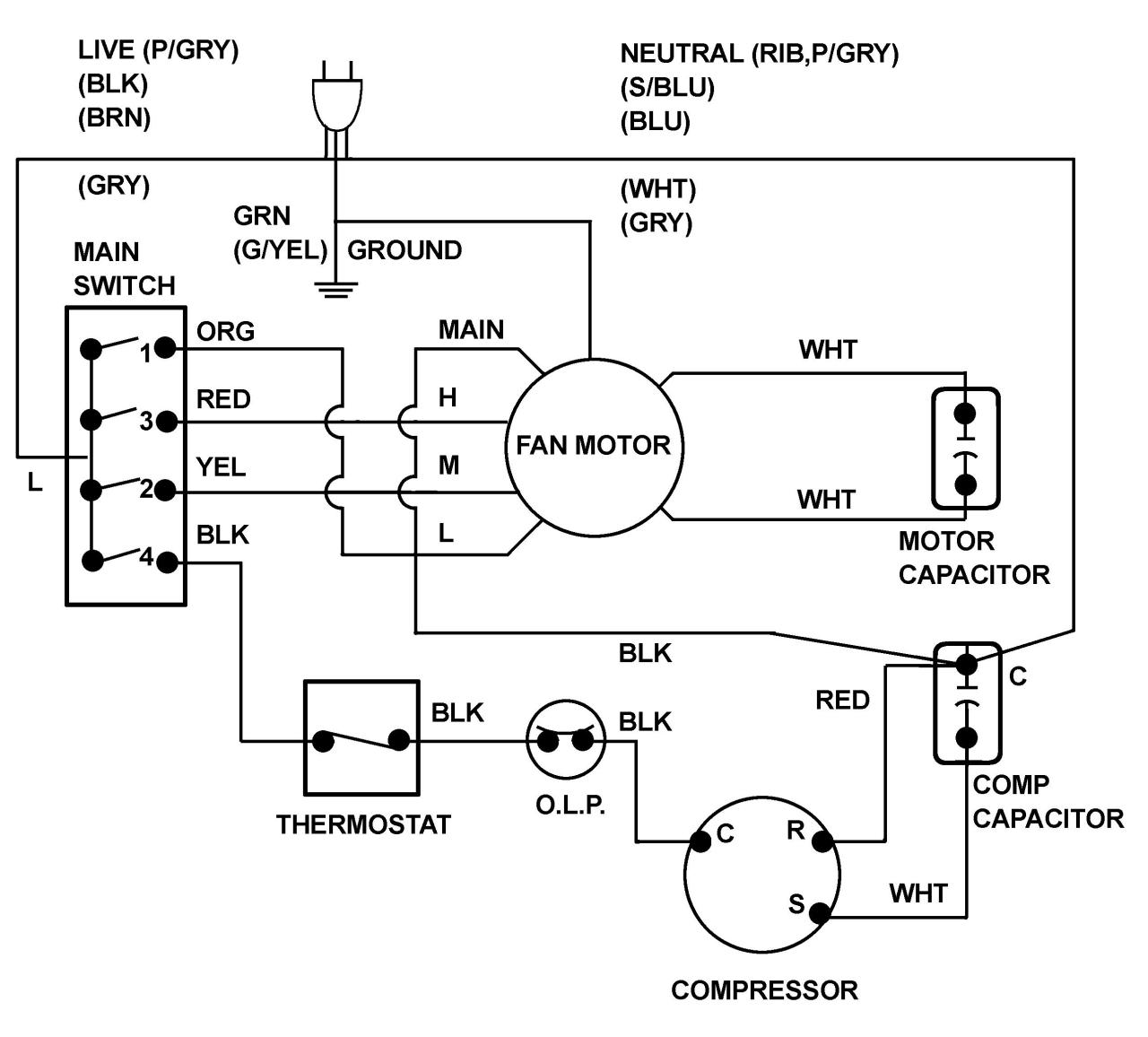
Blower Motor Wiring Diagram Ac Condenser Fan Motor Wiring Diagram Air Compressor Pressure Switch Compressor Ac Condenser

60 Beautiful Motor Starter Wiring Diagram Electrical Circuit Diagram Circuit Diagram Electrical Wiring Diagram

Brushless Motor Wiring Diagram Diagram Arduino Power

Sample Image Capacitor Wiring Diagram Car Audio 3 Wire Well Pump Wiring Diagram Inspirational Electric Motor 16 Capacitor Electrical Diagram Diagram Car Audio

Electric 2 Speed Wiper Motor Diagram 1966 Chevy Truck Chevrolet Classic Chevy Trucks
Pin On Electrical Diagrams Engineering

Park Switch And Windshield Wiper Wiring Diagram With Washer Relay Coil In Wiring Diagram Wiper Motor Chevy Trucks Electrical Diagram Car Wiper

Ac Condenser Fan Motor Wiring Diagram 4 Wire Beautiful For New 7 Fan Motor Electric Cooling Fan Electric Fan

22 Stunning Electrical Switch Wiring Diagram Bacamajalah Electrical Switch Wiring Electrical Wiring Diagram Electrical Switches

Bodine Electric Motor Wiring Electric Motor Types Of Electrical Wiring Electrical Circuit Diagram

4 Wire 240 Volt Wiring Diagram Electric Motor Electrical Wiring Diagram Motor

3 Phase Motor Wiring Diagrams Non Stop Engineering Electrical Circuit Diagram Electrical Diagram Electrical Wiring Colours