Wall behind the thermostat. On a further call for cooling the thermostat signals for the fan to speed up from its.
Cool Intertherm Thermostat Wiring Schematic Photos Thermostat Wiring Trane Heat Pump Hvac Thermostat
Wiring diagrams – Johnson Controls – TEC3030-1x-xxx – TEC3031-1x-xxx – TEC313x-14-xxx – TEC3330-1x-xxx – TEC3331-1x-xxx – TEC3630-1x-xxx – TEC3631-1x-xxx – Fan Coil Thermostat – Network Thermostat – Wireless Thermostat – TEC3000 Series Thermostats for Packaged Rooftop and Heat Pump with Economizer.

Fan Coil Unit Thermostat Wiring Diagram. I have found plenty of 3 speed seasonal change over thermostats but they are all 120v. I have a Nest 3rd Gen I was hoping to hook up here but the wiring is a bit different from. Do not use it where the space temperature is outside of the device operating range.
Formers by using a thermostat with isolat-ing contacts. Fan Coil Thermostats HW OS No. This is usually a duct around 100mm in diameter.
The unit must be GROUNDED to prevent possible hazard due to insulation failure. Match and connect wires to terminals on thermostat. UNITS WITH HYDRONIC COOLING COILS.
Operation at low temperatures can cause fan coil damage. Norcold Power Board Wiring Diagram. Fan Coil Unit.
VAQ RAQ SERIES FAN COIL UNIT Figure 1 WIRING DIAGRAM GENERAL The manufacturer assumes no respon-sibility for equipment installed in violation of any code requirement. Remove the eyebrow board from the eyebrow assembly as shown in figure 11 57. Thermostatic Controls – Fan coil unit with aquastat – installing a smart thermostat – Hi everyone New member and new home owner here – thanks for welcoming me.
Field wiring to the electric junction box shall have a temperature rating of no less than 75 C. Mounting and Wiring CAUTION Equipment damage hazard. Re-attach thermostat cover to back plate.
Turn on power to unit. This Is The Boiler Section Of A Dometic Cooling Unit For An Rv. Push excess wiring into wall.
SEQUENCE OF OPERATIONS 6 Fan Coil Unit Control Applications May 2001 2001 Environmental Technologies Inc. Concealed pipes or chimneys. T01 THERMOSTAT CODE For a 2-pipe system.
On the thermostat and the room temperature. Fan Coil Unit Diagram Non-Ducted Recirculation The below shows a typical fan coil unit that will use the ceiling as a returnrecirculation plenum. I have an IEC fan coil unit FXY – Vertical Cabinet Series to be exact.
Thermostat CrestronThe diagram below shows how a basic 4-wire thermostat is connected as indicated by the color code chart above. Hl series d horizontal low profile fan coil unit. We recently bought a high-rise condo with a fan coil unit ACheat.
I have further analyzed the wiring between the fan coil units and thermostats and it definitely looks like temporary stuff. Thermostat for IEC Fan Coil Unit. Unit-Mounted Mechanical Thermostat With 4-Position Fan Switch This unit-mounted option combines the four-position fan switch described above with a mechanical thermostat.
120V-1PH-60HZ SUPPLY 24V FAN RELAY GND PUMP WHT WHT BLK WHT N FAN MOTOR PUMP. All electrical wiring must not touch the water piping or any moving parts of the fan motors. BOn a call for cooling the thermostat signals for the heating control valve to modulate toward the closed position.
A display of two dashes for the Room Temp. The thermostat has been programmed for the incorrect type of fan coil system or the fan coil is not wired to the thermostat correctly. The thermostat will receive power from the fan coil unit.
Since this is going to be exterior the look of 120v wire going on the outside of. Applications Features Power System Switch Fan Options Fan Modes 2-pipe 4-pipe Auto Changeover Auto Changeover Deadband Adjust VerasaSpeed Fan Ramping Auto Fan Reset Digital Display PI Control Remote Setback No. Fan coil unit thermostat wiring diagramfcu thermostate connectionhoneywell thermostat connection.
Of Fan Speeds Adjustable MinMax Setpoint Activity Sensing Freeze Protection Option F C 24 Vac. I am especially concerned about possible confusion between the fancoils C terminal fancoil to water control valve and Y terminal thermostat to fancoil for water control valve. The controller prevents the fan coil unit from operating in one mode if the required water.
In this video i am going to show you how to make control wiring for AHU and FCU using with honey well 24 volts modulating Type thermostat honey well thermos. There could be instances where a fresh air duct is connected to the unit to provide a minimal fresh air volume. In the most basic system this functionality is provided by use of a fan center relay and the low voltage wiring to the thermostat now will require a minimum of three wires for heat only units and four wires for heat cool fan for control.
Ensure that the rated voltage of the unit corresponds to that of the name plate before commencing wiring work according to the wiring diagram. Each fan coil unit is provided with a data plate stating voltage and ampacity. Bestco technology ltd fan coil module fcu t02 with bacnet climactrl thermostat for iec unit mlm controller wiring hvac problem solver replacing honeywell t651a tstat beca bac 2000 black screen four pipe zl hv60ar 100 240vac r485 communication byc07 icp das 24v t6865 0 10v output trane mcd524 50hz line type ac 220v room mechanical help electrician.
Thermostats Crestron CHV-TSTAT and CHV-THSTAT Quick Installation Reference 1. The basic Heat AC System thermostat typically utilizes only 5 terminals. On Fan Coil Unit Thermostat Wiring Diagram.
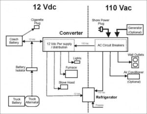
Currently it only has manual controls hi med low and manual valves. Refrigerator service manual 1200xx 120x imxx models about this manual this service manual provides maintenance diagnostic and repair information for norcold inc model. For two-pipe systems with a factory installed valve package it can be provided with a manual switch shown in picture to the right to change from heating to cooling.
This thermostat is not a safety device. Strip each wire at the end no more than 14 to prevent wires from shorting together. Seal hole in the wall to prevent drafts.
Also make certain that the water valve is wired toY1 the terminal. When the fan coil has reached the desired setpoint the fan will operate at medium speed and at regular intervals to ensure constant room temperature and lower sound. Infinet ex wireless thermostat fan coil unit 40 pages.
When 120v is switched to cooling wire pipe is cold fan would kick in because now thermostat knows its cooling season. Program the thermostat for a 2-pipe fan coil step 3 page 11 of the Owners Manual. Unit internal wiring is terminated in a junction box which is located on either the left or right hand side of the unit.
AThe Fan Coil Unit is controlled by a unit mounted controller provided by Mechanical Systems Controls Contractor MSCC. 120V Y 2 4 CAPACITOR IF REQD. Say the Tstat is set to 70F the season is heating pipes are hot outside temp jumps past 70F that Aquastat does not let the unit run fan because that 120v is on heating wire.
The Heat or Cool Only control type utilizes a wall or unit mounted Heating or Cool-ing thermostat which cycles the water control valve to maintain space temperature.
Single Stage Heat Pump Thermostat Wiring Diagram Thermostat Wiring Hvac Thermostat Carrier Hvac

Pin On Ceiling Fan Wiring Diagram

55 New Potential Relay Wiring Diagram Electrical Circuit Diagram Ac Capacitor Electrical Diagram

Intertherm Thermostat Wiring Diagram Wiring Forums Diagram Diagram Chart Electrical Wiring Diagram

Nordyne Air Handler Wiring Diagram Fan Circuit Free For Ac Model E2eb 015ha 2 With E2eb 015ha Wiri Thermostat Wiring Electric Furnace Electrical Wiring Diagram

3 Phase Split Ac Wiring Diagram Ac Wiring Air Compressor Pressure Switch Split Ac

Thermostat Wiring Explained Thermostat Wiring Hvac Thermostat Hvac Air Conditioning

Unique Combi Boiler Programmer Wiring Diagram Diagram Diagramtemplate Diagramsample Thermostat Wiring Diagram Thermostat

How To Wire A Harley Davidson Coil New Motorcycle Wiring Harley Davidson Harley

Goodman Air Handler Wiring Diagram Inspirational Thermostat Wiring Air Handler Goodman Heat Pump

Craftsman Riding Mower Electrical Diagram Wiring Diagram Craftsman Riding Lawn Mower I Need One For Craftsman Riding Lawn Mower Lawn Mower Riding Mower

Split Ac Full Electric Wiring Diagram Fully4world Fully4world Air Conditioning System Design Refrigeration And Air Conditioning Hvac Air Conditioning

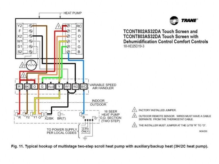
Trane Heat Pump Wiring Trane Heat Pump Heat Pump Thermostat Installation

50 Luxury 90340 Relay Wiring Diagram Thermostat Wiring Electrical Circuit Diagram Electrical Wiring Diagram

Unique Trane Heat Pump Thermostat Wiring Diagram Thermostat Wiring Electrical Diagram Trane Heat Pump

Inspirational Wiring Diagram Pioneer Diagrams Digramssample Diagramimages Check More At Https Nostoc Pioneer Car Stereo Car Stereo Car Audio Installation

Carrier Heat Pump Wiring Diagram Heat Pump Carrier Heat Pump House Wiring

Goodman Phk024 1f Wiring Diagrams Thermostat Wiring Trane Heat Pump Hvac Thermostat

Ac Wiring Diagram Of Window Airconditioner Ac Wiring Thermostat Wiring Electrical Wiring Diagram