Contact sensors have two. Wiring it wrong will create problems like it may give electric shocks when you press the push button short-circuit in the chime or the bell button or it may not produce the sound.
Unique Trane Heat Pump Thermostat Wiring Diagram Thermostat Wiring Electrical Diagram Trane Heat Pump
2The second diagram shows 3 grade 1 door contacts wired in series going to a zone The blue and yellow continue to the global tamper.

Door Contact Wiring Diagram. Familiarize yourself with the four most common doorbell push button chime and transformer circuits by taking a look at the diagrams below. WIRING CONNECTIONS SAMPLE 1 DOOR STATUS SWITCH OUTPUT Shown widoor fully closed SAMPLE 2 HARDWIRED PUSH PLATES WITH PUSH SIDE DOOR-MOUNTED SENSOR Terminal 4. Home Products About GRI Contact GRI Where to Buy Testimonials Whats New.
My PIRs are wired in the normally closed config. Contact sensors have two wires coming out of each sensor. Wiring diagrams sometimes called main or construc-tion diagrams show the actual connection points for the wires to the components and terminals of the controller.
Craftsman Garage Opener Wiring Diagram Wiring Diagram Craftsman Garage Door Opener Wiring Diagram By Hadir Published February. Door contact switch rear right 39. The following diagram shows an example of an IP access control system that uses a reader-controller.
Contact closes upon full door closed position. It shows the components of the circuit as simplified shapes and the power and signal connections between the tools. White Brown Grey or Black UL and ULC Approved 180-12 184-12 UL 10C Fire Rated Available in Closed Loop Open Loop and SPDT 34 and 1 Diameter Mounting.
I assumed theres two wires here that I need to wire into an available zone but which ones. They can be used as a guide when wiring the controller. A wiring diagram normally provides details concerning the family member placement as well as.
Electricity supply switches and of course locks. Typically doorbell chimes have three terminals labeled rear trans and front that correspond with each connection. Connect zones the same way youd connect a single sensor connecting the first and last wire in the series to GND and an input pin.
A wiring diagram is a streamlined traditional pictorial depiction of an electric circuit. The 10781076 Series Steel Door contacts are designed specifically for use in the steel doors commonly found in commercial building applications. If you print the diagram off and get some felt tip pens crayons colour the cables.
A wiring diagram is a simplified standard pictorial representation of an electrical circuit. Door contact switch rear left 38. This is an index page to some of the detailed wiring diagrams created by Networking and Telecommunications with initial assistance from Tech Electronics who has a very knowledge and personable staff.
Single Doorbell Push Button with a Single Chime. The design of this type of contactor is most advanced among all other types of contactors. Plug – burglar alarm wire.
The devil is in the details and this article provides the wiring diagrams you need to make your access control system work. Door and window contacts with built-in resistors are the absolute best and easiest way of placing the end of line resistor in that ideal position. Integral 32 and 63 State of Auxiliary Contacts 53-54 Wiring Diagrams 55-57 Type S AC Combination Magnetic Starters58-59 Class 8538 and 8539 58-59.
Plug – centre section to wire for on board computerburgiar alarm 43. A wiring diagram is a kind of schematic which uses abstract pictorial symbols to exhibit all the interconnections of components in the system. Door contact switch tront right 37.
Assortment of magnetic door contact wiring diagram. Im not using tamper and assume that the contact doesnt need power. S-N10 to N21 MSO-N10 to N21 and SR-N4 Air conditioner contactor wiring diagram inspirationa wiring diagram.
Shows the wires coming back from the contacts to the panel and zone 8 appears to be powered so is probably a PIR. Figure 1 is a typical wiring diagram for a three-phase mag-. The magnet housing isolates the magnet from the surrounding steel for maximum gap.
They show the relative location of the components. The unique housing design features a rugged unibody construction with flexible ribbed sides for quick secure installation without gluing. The following input pins on the Konnected device can be used for contact sensors.
Architectural wiring diagrams action the approximate locations and interconnections of receptacles lighting and enduring electrical facilities in a building. A wiring diagram is a simplified standard pictorial depiction of an electric circuit. Ive got a door contact that I want to wire into a Texecom premier elite panel and it comes with the following diagram.
Otherwise the arrangement wont function as it. The need to make a doorbell wiring diagram comes when you want to make it and supply it to your customers. Here I install a magnetic door contact on a PVC door and wire it to a Honeywell ADE Gen4 alarm panel.
When any one door or window in the zone is open the zone reports as open. Door contact switch front left 36. You always try to avoid any mistakes and try everything.
Magnetic door contacts are normally wired to the entr. A wiring diagram is a streamlined traditional pictorial depiction of an electric circuit. Common for both Door Open Closed Status.
Wiring Diagram Book A1 15 B1 B2 16 18 B3 A2 B1 B3 15 Supply voltage 16 18 L M H 2 Levels B2 L1 F U 1 460 V F U 2 L2 L3 GND H1 H3 H2 H4 F U 3 X1A F U 4 F U 5 X2A R Power On Optional X1 X2115 V. This is the most basic doorbell setup option. The 10781076 Series Steel Door contacts are designed specifically for use in the steel doors commonly found in commercial building applications.
Magnetic locks also referred to as mag locks or maglocks for short rely on a constant flow of electricity to stay sealed. Rear window heater 42. Garage door sensor wiring diagram Garage Door Wiring Instructions Wonderful Sensor Inspirations Mimolite For And Magnetic Contact Devices Sensors Diagram In Craftsman Opener.
As a review the advantage of IP access control systems is that everything is located at the door. 180 Series 34 and 1 Steel Door Recessed Switch Sets 180-12 184-12 8080-T Lifetime Warranty Colors. Boot lid contact 40.
Door Closed status switch. When that power is cut the magnet essentially turns off undoing. Panel in the wiring loop the greater the possibility of compromise of the unprotected loop wiring after the resistor position.
Plug for light diode 45. Much like the door access control system diagram above the mag lock wiring diagram relies on a few simple basics. Magnetic door contact wiring diagram wiring DG85 motion sensor to wired alarm panel.
If a diagram is not found that exactly addresses the type of door and the exact set of features present please contact Steven Coffman and a custom. Magnetic Lock Wiring Diagram.

Installing Turn Signals Motorcycle Wiring Electrical Diagram Electrical Wiring Diagram

110cc Chinese Atv Wiring Diagram Schaferforcongressfo Motorcycle Wiring Pit Bike Trailer Wiring Diagram

Pin En Wiring Diagram

Installation Of Single Pole 3 Way 4 Way Switches Wiring Diagram Electrical Wiring Home Electrical Wiring Electrical Switch Wiring

Wire Harness Wiring Cdi Assembly For 50 70 90 110cc 125cc Atv Quad Coolster Go Kart Wish In 2022 Motorcycle Wiring 90cc Atv Chinese Scooters

Car Alarm Wiring Diagram On Security Download Throughout Diagrams With On Car Alarm Installation Wiring Diagr Car Alarm Viper Car Alarm

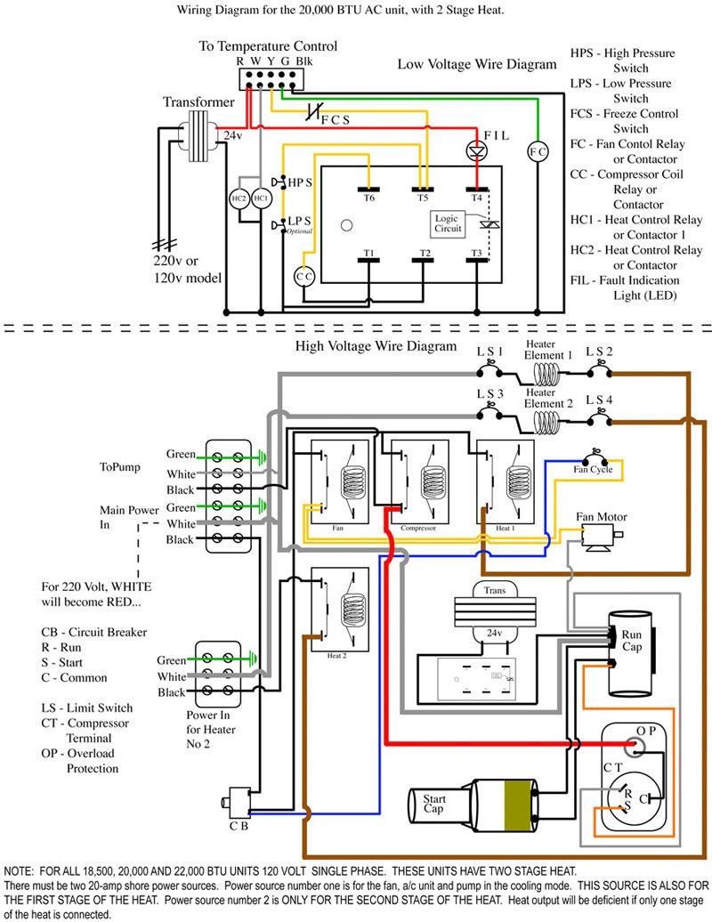
Ac Wiring Diagram Of Window Airconditioner Ac Wiring Thermostat Wiring Electrical Wiring Diagram

Power Window Wiring Diagram Trailer Wiring Diagram Automotive Electrical Motorcycle Wiring

17 Simple Car Wiring Diagrams Design Https Bacamajalah Com 17 Simple Car Wiring Diagrams Design Car Alarm Electrical Wiring Diagram Automotive Electrical

18 Car Central Lock Wiring Diagram Car Center Electrical Circuit Diagram Car Door Lock

Lewmar Windlass Wiring Diagram Upgrade Windlass Power Wiring Of Lewmar Windlass Wiring Diagram With Windlass Wiring Diagram For Windlas Diagram Power Wire Wire

150cc Scooter Wiring Diagram 50cc Scooter Stator Wiring Diagram 150cc Scooter Electrical Diagram Chinese Scooters

Inspirational Wiring Diagram Pioneer Diagrams Digramssample Diagramimages Check More At Https Nostoc Pioneer Car Stereo Car Stereo Car Audio Installation

Marine Power Inverter Wiring Diagram Trailer Wiring Diagram Diagram Wire

60 Beautiful Motor Starter Wiring Diagram Electrical Circuit Diagram Circuit Diagram Electrical Wiring Diagram
Push Button Ignition Switch Wiring Diagram New Boat Wiring Kill Switch Electrical Wiring Diagram

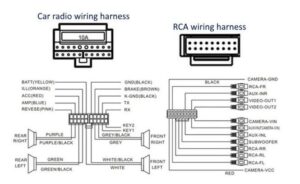
Car Speaker Wire Harness Diagram Electrical Wiring Diagram Car Ecu Trailer Wiring Diagram

Harley Davidson Wiring Diagram Agnitum Me And At Harley Wiring Diagram Pocket Bike Sportster Home Electrical Wiring

Bell Systems Wiring Diagram Entry Doors Diagram Wire