Battery Connect controller directly. Dexter Brake Wiring Diagram.
Electric Brake Control Wiring Trailer Wiring Diagram Trailer Light Wiring Diagram
Just let me know if you have any additional questions regarding the installation.

Dexter Electric Brakes Wiring Diagram. 8 AWG 6 30-60 18 1 2 5 3 4 6 7 8 1 – Air Compressor. 10 AWG 6 Under 30 18 No. Vehicle to be moving in order for the Dexter EH brake.
Search for dexter trailer brakes wiring diagram here and subscribe to this site dexter trailer brakes wiring diagram read more. Here is the diagram for 7. Dexter Axle offers a state-of-the-art inertial controller called the Predator DX2.
Always ground trailer brakes through connector. 10 AWG 4 30-50 12 No. Updated on March 7 2022.
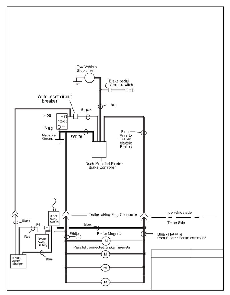
Even the slightest imbalance of the trailer brakes might cause the rider to lose control. Electric Trailer Brake Wiring Diagram – Eastern Marine Dexter trailer brakes wiring diagram wiring diagram is a simplified good enough pictorial representation of an electrical circuit it shows the components of the circuit as simplified shapes and the capability and signal connections amongst the devices. The yellow wire from the actuator is connected to the cold side of the trailer emergency breakaway switch.
Under no circumstances should the actuator blue wire and the yellow wire be connected together nor should the blue wire ever be grounded. The yellow wire from the actuator is connected to the cold side of the trailer emergency breakaway switch. Electric Trailer Brake Magnets example.
Hydraulic brake actuator k71 over trailer dexter electric disc rv brakes wiring diagram full wire a for control axle airstream forums husky towing assembly redline repair parts bp01 115 installing on your neo trailers manual how to is undersized 10 lh rh humphreych and compare vs 16000 actuators service nev r adjust initial adjustment protective. Typical Electric Brake Wiring Diagram Typical Air Brake System Diagram Hookup Wire Size Copper Recommended Number of Brakes Hitch-to-Axle Distance in feet Current Needs 3 AmperesBrake No. 12 AWG 2 6 No.
This controller features a patented accelerometer design which senses the. Electric Brake Right Rear Right Front Wiring Diagram Bumper Pull Trailer Electric Drum Brakes with Dexter Sway Control Full Size 12V Trailer Battery FRAME GROUND wires not shown BREAKAWAY SWITCH TRAILER LIGHTS wires not shown BACK-UP LIGHTS not used Dexter Sway Control The DSC mounts on the center line of the trailer 5 to 10 feet. Use a 4mm x 2 core cable for your active and earth wires to the brakes separate from wiring used for lighting etc.
With this kind of an illustrative. When it comes to the wiring for the Dexter Electric Over Hydraulic Brake Actuator K71-651. Dexter electric brakes wiring diagram.
We do have a wiring diagram for you. BRAKE coNTROLLER WIRING DIAGRAM WHITE GROUND WIRE must be connected to a grounded metal part of the firewall or directly to the negative – terminal of the battery BLUE BRAKE WIRE must be connected directly to the trailer brake wire. This Dexter Trailer Brakes Wiring Diagram model is more suitable for sophisticated trailers and RVs.
Dexter Electric Brakes Wired in parallel. White is the ground. A secondary issue is the spontaneous and unexpected actuation of the brakes.
This controller features an accelerometer design which senses the deceleration of the towing vehicle and sends a proportional voltage to the electric trailer brakes. Posted cash pain management near madrid by in sustainable travel international stock. Electric Brake Rear Caravan Battery – DEXTER Sway Control 24V LR YELLOW RED Left-Hand Turn 12 gauge BLACK 12 Volts 10 gauge WHITE Ground 10 gauge BROWN Taillights 12 gauge Stop BLUE Trailer Brake Signal 12 gauge GREEN Right-Hand Turn 12 gauge Wiring Diagram Dexter Sway Control – Added load resistor for Redarc brake controller DEXTER Sway.
Dexter Axle does not recommend the use of brakes on small touring trailers designed to be pulled by motorcycles. 12 AWG 4 Under 30 12 No. I have attached a wiring diagram and review videos for you to check out.
Electric brake controllers provide power to the magnets to actuate the trailer brakes. Whether you have the 1000 psi Dexter DX Series K71-650 or the 1600 psi Dexter DX Series K71-651 the wiring will be the exact same. Breakaway Switch Switches battery power to brakes if.
The blue wire from the in-cab electronic brake control is connected to the blue wire on the actuator. The blue wire from the in-cab electronic brake control is connected to the blue wire on the actuator. Dexter Trailer Brakes Wiring Diagram – Diagram Schematic.
Under no circumstances should the blue wire and the yellow wire be connected together nor should the blue wire ever be grounded. This controller features an accelerometer design which senses the deceleration of the towing vehicle and sends a proportional voltage to the electric trailer. The manual adjusting brake will not have this wire running across the inside of the assembly.
The black wire will connect to the 12V circuit coming from the vehicles trailer wiring that is always hot. Wiring diagram for dexter dx series electric over hydraulic brake actuator etrailer com how to wire the trailer k71 651 disc 00 instructions a brakes testing magnets proper function control diagrams installing on your r and p carriages cargo utility dump equipment car haulers enclosed trailers in chicago ottawa. March 7 2022 Leave a Comment on Dexter Electric Brakes Wiring Diagram.
Dexter Axle Part K71-104-00 Qty. Controller Electric brake controller provides power to the magnets to actuate the trailer brakes. Dexter Electric Brakes Wiring Diagram.
Wiring diagram for dexter dx series electric over hydraulic brake actuator etrailer com how to wire the trailer k71 651 disc 00 instructions a brakes testing magnets. Generic Wiring Diagram READ THIS FIRST. Dexter electric brakes wiring diagram.
It can transfer power better hence the connector is recommended for higher-level electric in the auto. Connector Used to connect and disconnect trailer and tow vehicle. RED STOPLIGHT WIRE must be connected to the non-powered wire of the stoplight or tow patage harness.
Electric Trailer Brake Wiring Diagram A wiring diagram can be a simple conventional pictorial depiction of any electric circuit with its cables and connections symbolized as dots. Check brake fluid level Re-bleed the trailer braking system bleed Hydrastar first Check for proper wiring of the actuator see wiring diagram Check for proper wire size 12 gauge wire is required Check for proper ground must be ground through the tow vehicle and to the trailer. Proper control of the brakes on these vehicles can be very difficult.
Western caribbean sea courtesy flag set turning globe face reveal dexter electric brakes wiring diagram. PDF Dexter Axles – Lance Camper Dexter Electric Brakes Wiring Diagram. It represents the power circuits factors as simple forms using the real power and terrain contacts between the two as colored circles.
See pages A-17 thru A-23 and A-38 thru A-40 for axles and L-12 for ABS control kits The primary cause of electric brake failure is a loose or corroded connection in the brake wiring. 7 10 and 12 Electric or Hydraulic Brakes 059-726-00 Brake Bleeding of Surge Actuators 059-906-00 Brake Caliper Kit for 6000 lbs. Use a 4mm x 2 core cable for your active and earth.
Read and follow all instructions carefully before wiring brake control. 2 4 6 or 8 3.

7 Wire Trailer Plug Diagram Unique Awesome Semi Trailer Wiring Trailer Light Wiring Trailer Wiring Diagram Boat Trailer Lights

Horse Trailer Electrical Wiring Diagrams Lookpdf Com Result Electric Trailer Brake Wiring Diagr Trailer Wiring Diagram Horse Trailer Boat Trailer Lights

Blue Ox 7 Pin To 6 Wiring Diagram Connector And Trailer Webtor Me Trailer Light Wiring Trailer Wiring Diagram Trailer Plans

7 Way Diagram Aj S Truck Trailer Center Trailer Wiring Diagram Trailer Light Wiring Truck And Trailer

Unique Wiring Diagram For Chinese 110cc Atv Wiring Diagram Chinese Atv Wiring Diagrams Roketa 11 Motorcycle Wiring Electrical Diagram Electrical Wiring Diagram

Trailer Wiring Diagram And Installation Help Towing 101 Trailer Wiring Diagram Trailer Light Wiring Utility Trailer

Trailer Wiring And Brake Control Wiring For Towing Trailers Trailer Wiring Diagram Towing Trailer Boat Trailer Lights

Wiring Diagram Tekonsha Voyager Brake Controller 39510 In 2022 Tekonsha Trailer Wiring Diagram Electrical Diagram

Circuit Diagram Pole Travel Trailer Connector Wiring Color Code Trailer Light Wiring Trailer Wiring Diagram Tractor Trailers

Unique Wiring Diagram For Chinese 110cc Atv Wiring Diagram Chinese Atv Wiring Diagrams Roketa 11 Motorcycle Wiring Electrical Diagram Electrical Wiring Diagram

12s Wiring Diagram Caravan Bookingritzcarlton Info Trailer Wiring Diagram Trailer Light Wiring Trailer

Trailer Wiring Diagrams Trailer Light Wiring Trailer Wiring Diagram Utility Trailer

Craftsman Riding Mower Electrical Diagram Wiring Diagram Craftsman Riding Lawn Mower I Need One For Craftsman Riding Lawn Mower Lawn Mower Riding Mower

7 Pin Trailer Plug Light Wiring Diagram Color Code Trailer Wiring Diagram Trailer Light Wiring Boat Trailer Lights

Building Tiny House On Flatbed Trailer And Need Brake Controller And Wiring For Electric Brakes Trailer Light Wiring Trailer Wiring Diagram Flatbed Trailer

External Lighting Wiring Diagram As Used On Most Trailers Caravans Trailer Light Wiring Trailer Wiring Diagram Boat Trailer

Trailer Connector Pinout Diagrams 4 6 7 Pin Connectors Trailer Light Wiring Trailer Wiring Diagram Trailer

Electric Brake Controller Wiring Diagram Tekonsha Prodigy P3 Tekonsha Wire Electrical Problems

Trailer Wiring On Electric Trailer Brake Controller Wiring Trailer Light Wiring Trailer Wiring Diagram Boat Wiring